The steps 1 to 12 of this NSX-T Installation series focused on the setup of the NSX-T Datacenter components i.e. NSX-T Management Cluster, Host and Edge Transport Nodes. From, Step 13 onwards, the focus shifted to building logical network topology that I alluded to in Step 0 – High Level Design.
Links to all the steps of the Second Phase for quick jump:
The previous step, discussed VLAN Segments and step-by-step instructions on how to configure one. This blog is part of the Second Phase i.e. building the logical network topology and “Step 17” of the NSX-T Installation series, in which we will discuss T0 (Tier-0) Gateway, its considerations, SR (Service Router), DR (Distributed Router), followed by step-by-step instructions on how to create an active-active T0 Gateway.
The image below highlights the logical entity of the “Routing Design” this step focuses on:
—————————————————————————————————————————————————— But before we proceed, I would encourage you to briefly skim through my other blogs below, which you may find useful for this step:
It is assumed that you have NSX-T Management Cluster deployed, Host and Edge Transport Nodes configured and ready to use. If not, please refer the steps 1 to 12 in this NSX-T Installation series for guidance.
If you are deploying this in your home lab or performing a PoC in a nested vSphere Environment, I would also suggest you have a quick glance of my blog Home Lab Setup – Nested ESXi Host’s networking for NSX-T. ——————————————————————————————————————————————————
A Tier-0 Gateway performs the functions of a Tier-0 logical router. It has downlink connections (auto-plumb) to Tier-1 Gateway(s) [created in Step 13] and uplink connections to physical networks.
NSX-T v2.4 introduced quite a lot of changes, one of them was the new UI i.e. introduction of the “Simplified UI” (also known as Policy UI) and “Advance UI” (also known as Manager UI). If you are familiar with the previous versions of NSX-T (v2.3 and before), the “Tier-0 Router” is now referred to as “Tier-0 Gateway” in the new “Simplified UI” but is referred to as “Tier-0 logical router” in the “Advance UI“.
Background: Each logical router contains a services router (SR) and a distributed router (DR). A DR is distributed across all transport nodes that belong to the same transport zone and an SR is centrally instantiated on the Edge Appliance(s). An SR instance is required for services that cannot be distributed i.e. Physical Connectivity, NAT, DHCP, Load Balancers, etc.
A DR component for the Tier-0 Gateway is instantiated on all Transport Nodes when a T1-Gateway is connected to it.
While an SR component for the Tier-0 Gateway is instantiated on the Edge Nodes when Physical routing, DNAT, Edge firewall, etc. services are required.
Auto Plumbing of T1 SR to T0 DR is done by “Inter-Tier” LS/Segment (VNI 65549) using 100.64 subnet (reserved)
Auto Plumbing of DR to SR is done by “Transit Segment” LS/Segment (VNI 69639) using 169.254 subnet (reserved)
Tier-0 Gateway Considerations:
Only One (1) Tier-0 gateway or logical router is supported per Edge Node
High availability (HA) of a Tier-0 Gateway can be either active-active (ECMP) or active-standby
Stateful services i.e. NAT, Firewall, VPN, etc. are NOT supported in an active-active (ECMP) mode
After you create the gateway, the HA mode cannot be changed
HA VIP on the active-standby is available from v2.5 onwards
If route redistribution is configured, only two groups of sources can be used i.e. Tier-0 subnets and advertised tier-1 subnets.
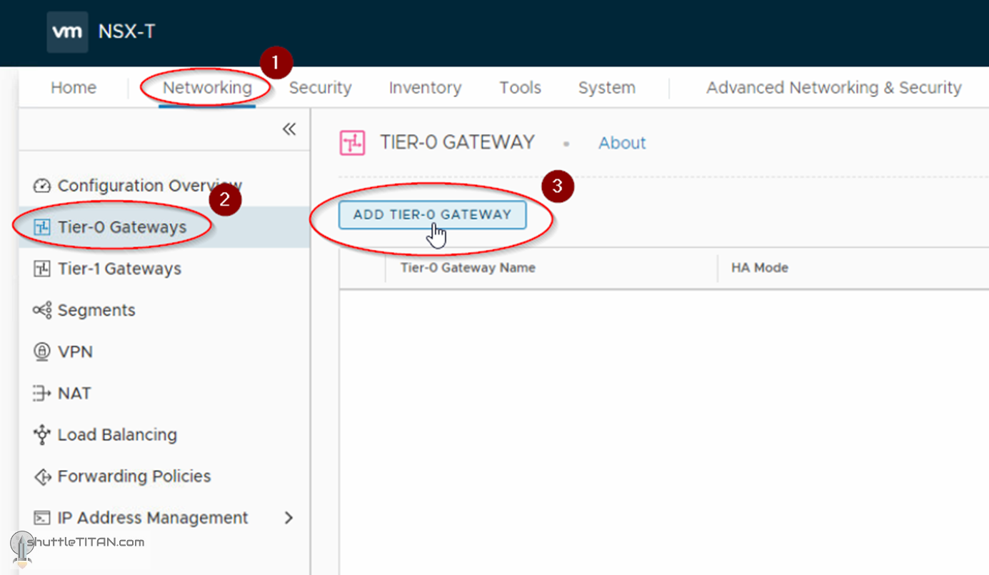
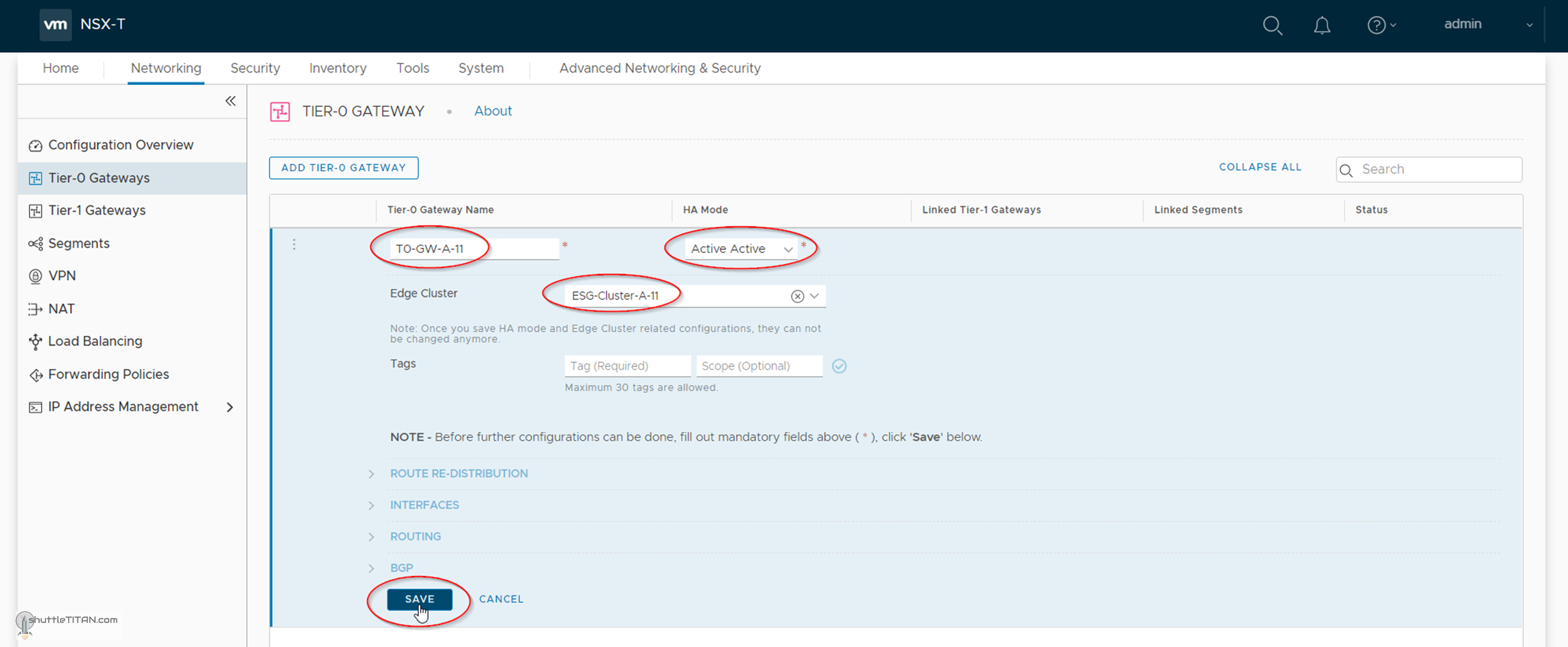
2. Specify the name as T0-GW-A-11, select “Active-Active” as Ha Mode and the Edge Cluster as ESG-Cluster-A-11 (created in Step 12) and click SAVE:
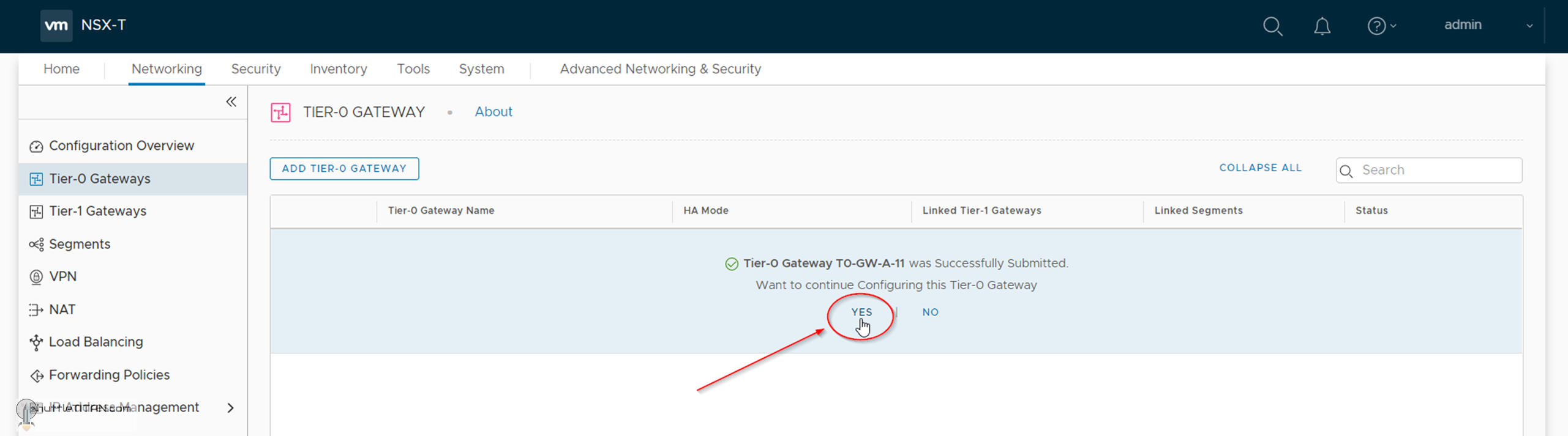
3. Click “Yes” when asked to continue configuring the Tier-1 Gateway:
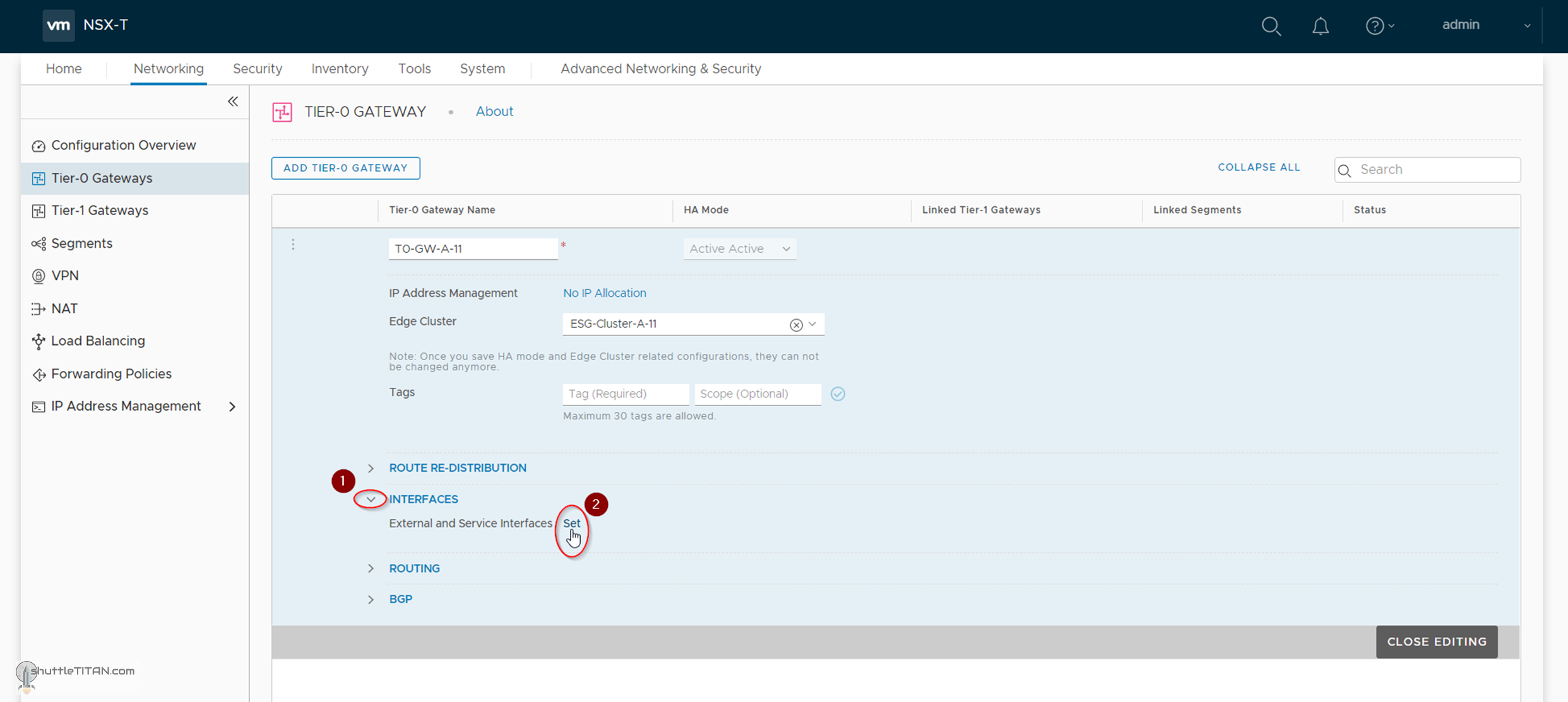
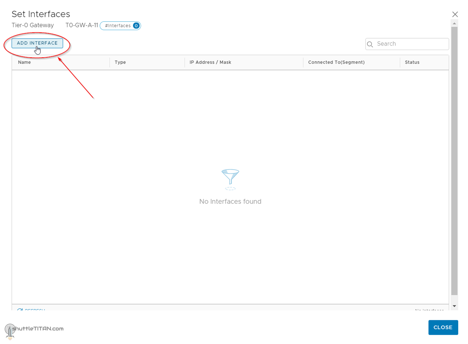
4. Click “Interfaces” and then “Set”:
5. Click “ADD INTERFACE”
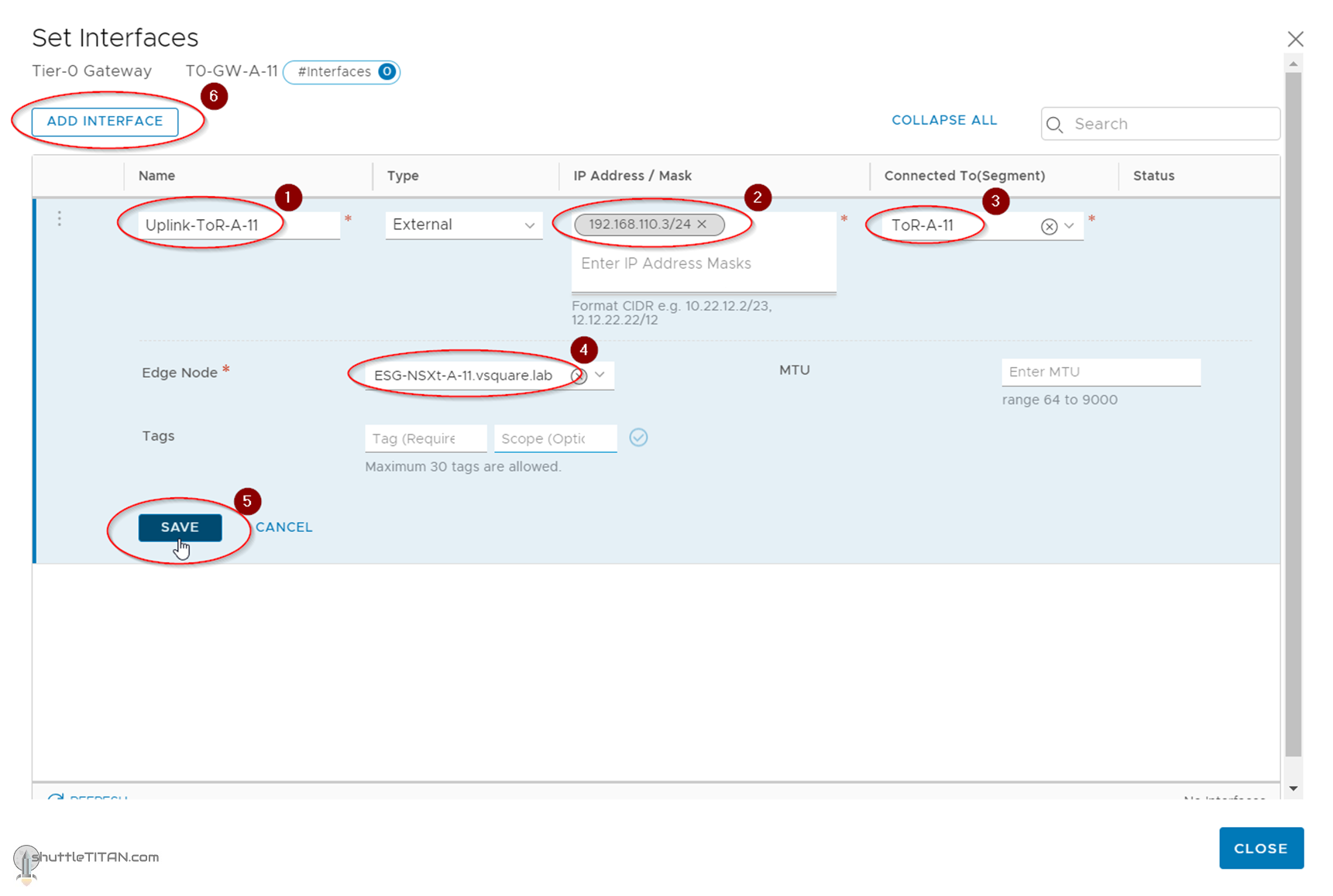
6. Specify the name as Uplink-ToR-A-11, IP, Connected to Segments as ToR-A-11 (created in the previous step), Edge Node as ESG-NSXt-A-11 (deployed in Step 10), Click “SAVE”. Click “ADD INTERFACE” again:
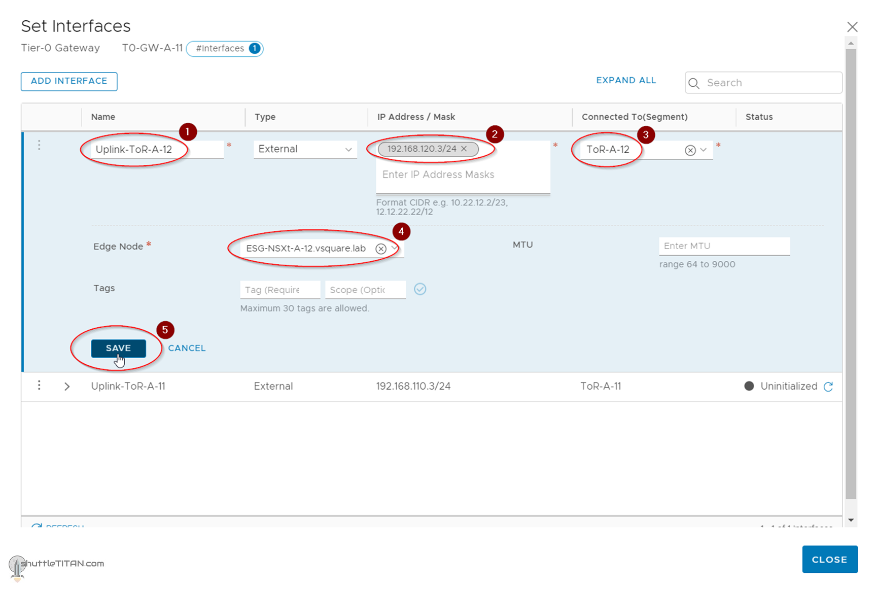
7. This time specify the name as Uplink-ToR-A-12, IP, Connected to Segments as ToR-A-12 (created in the previous step), Edge Node as “ESG-NSXt-A-12” (deployed in Step 10), Click “SAVE”:
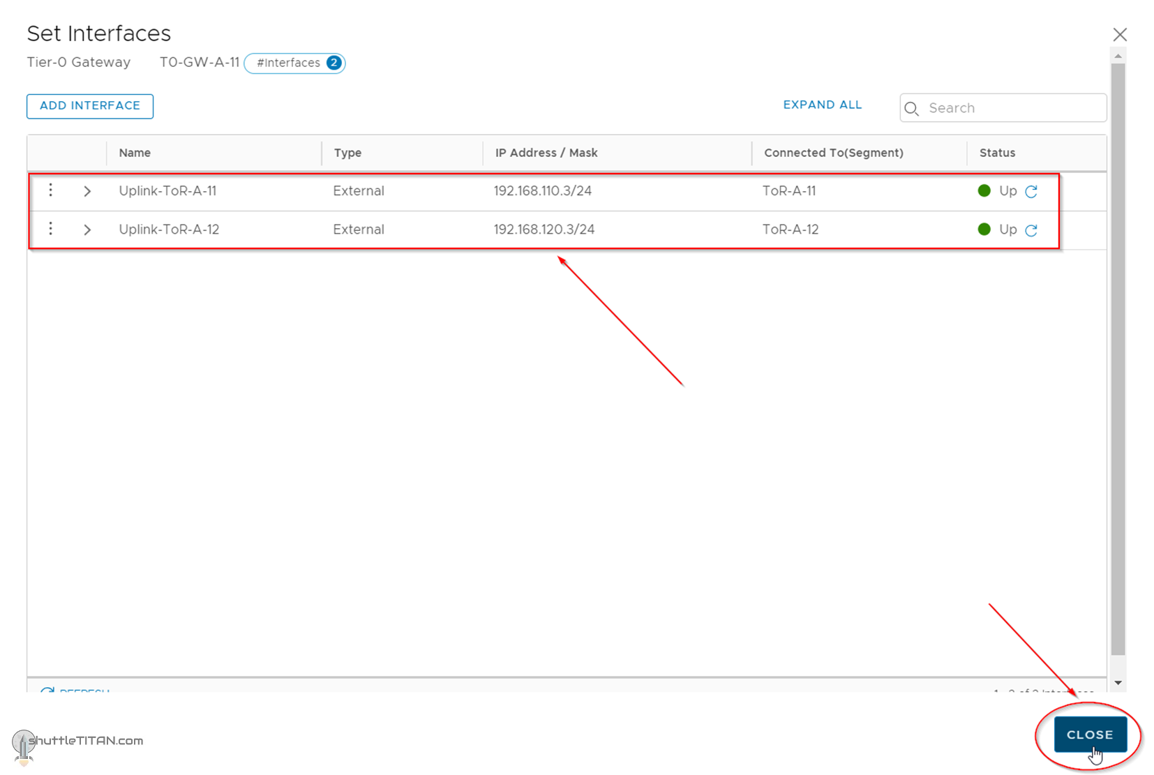
8. Both Interface should now list and show the status “Up”:
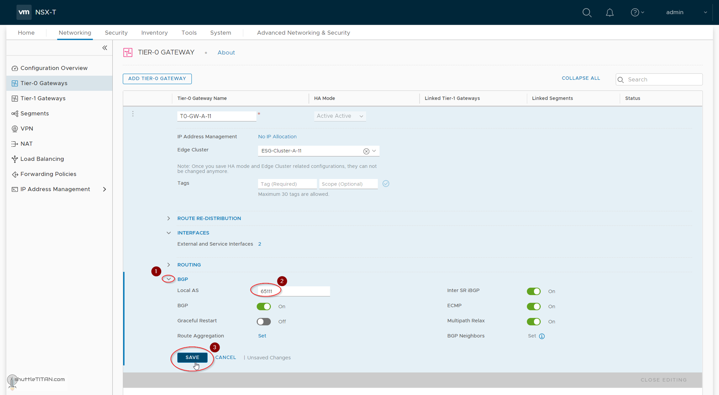
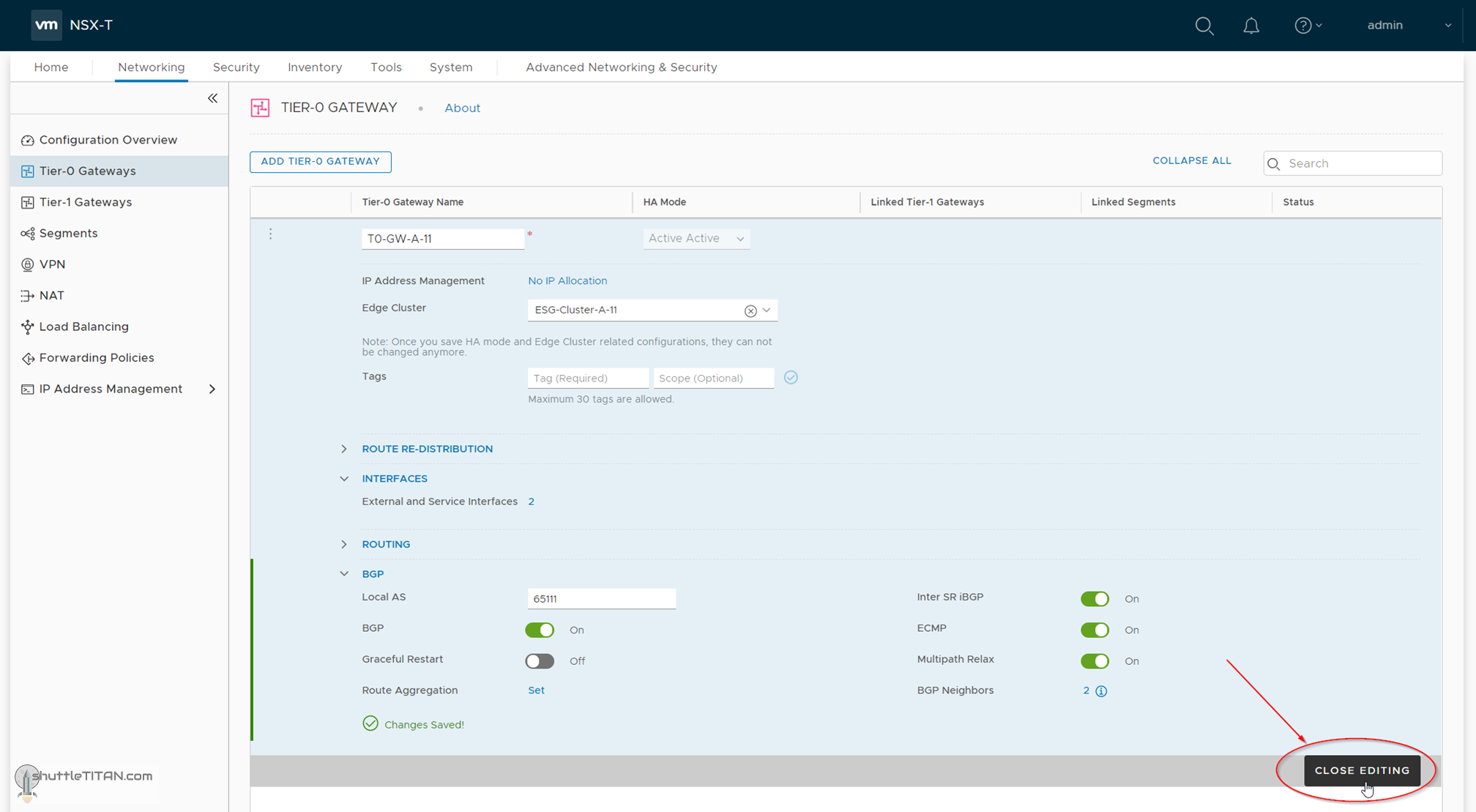
9. Click BGP, Specify the Local AS number as 65111, Click “SAVE”:
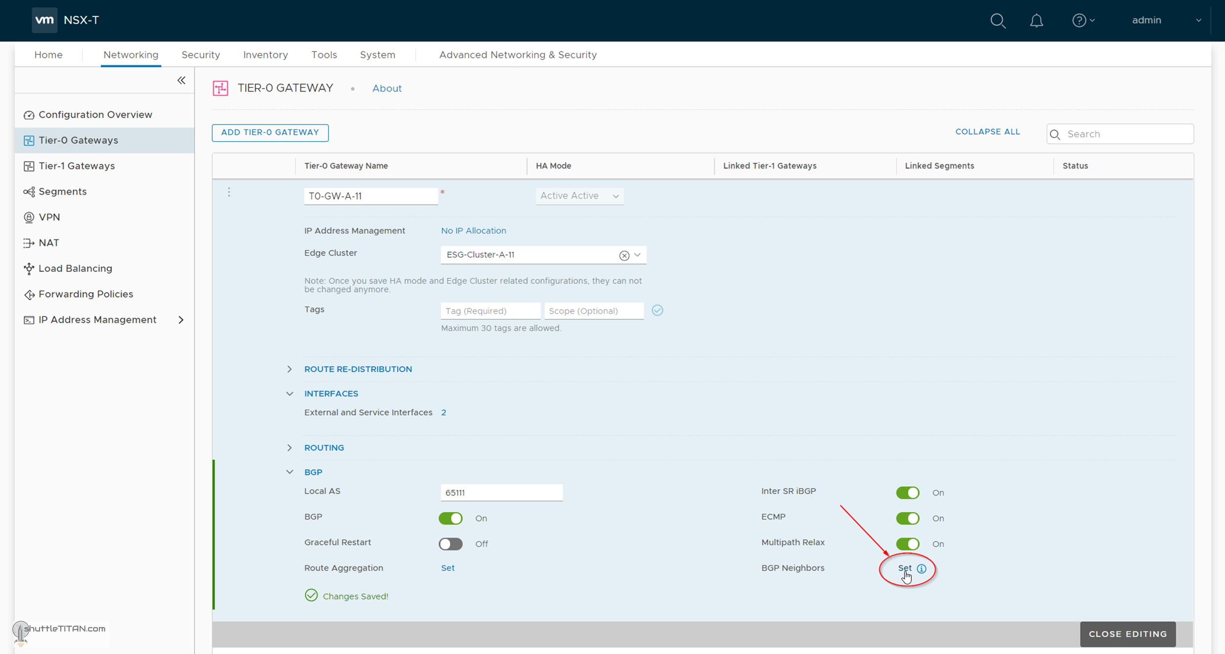
10. Click “SET” next to BGO Neighbors:
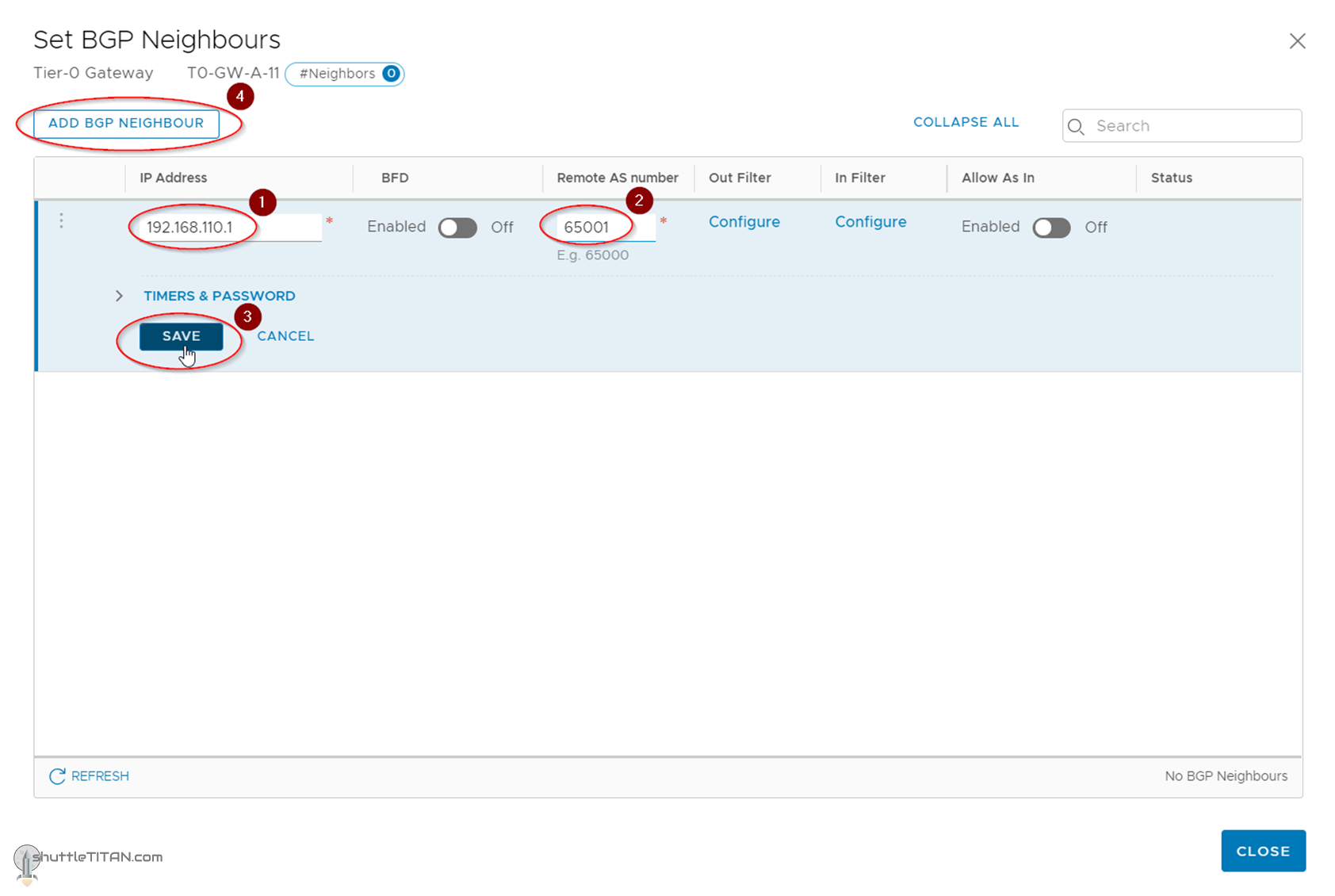
11. Click “Add BGP NEIGHBOURS”:
12. Specify the IP Address of the ToR (Physical Switch) interface, Remote AS number, Click “SAVE”. Click “Add BGP NEIGHBOURS” again:
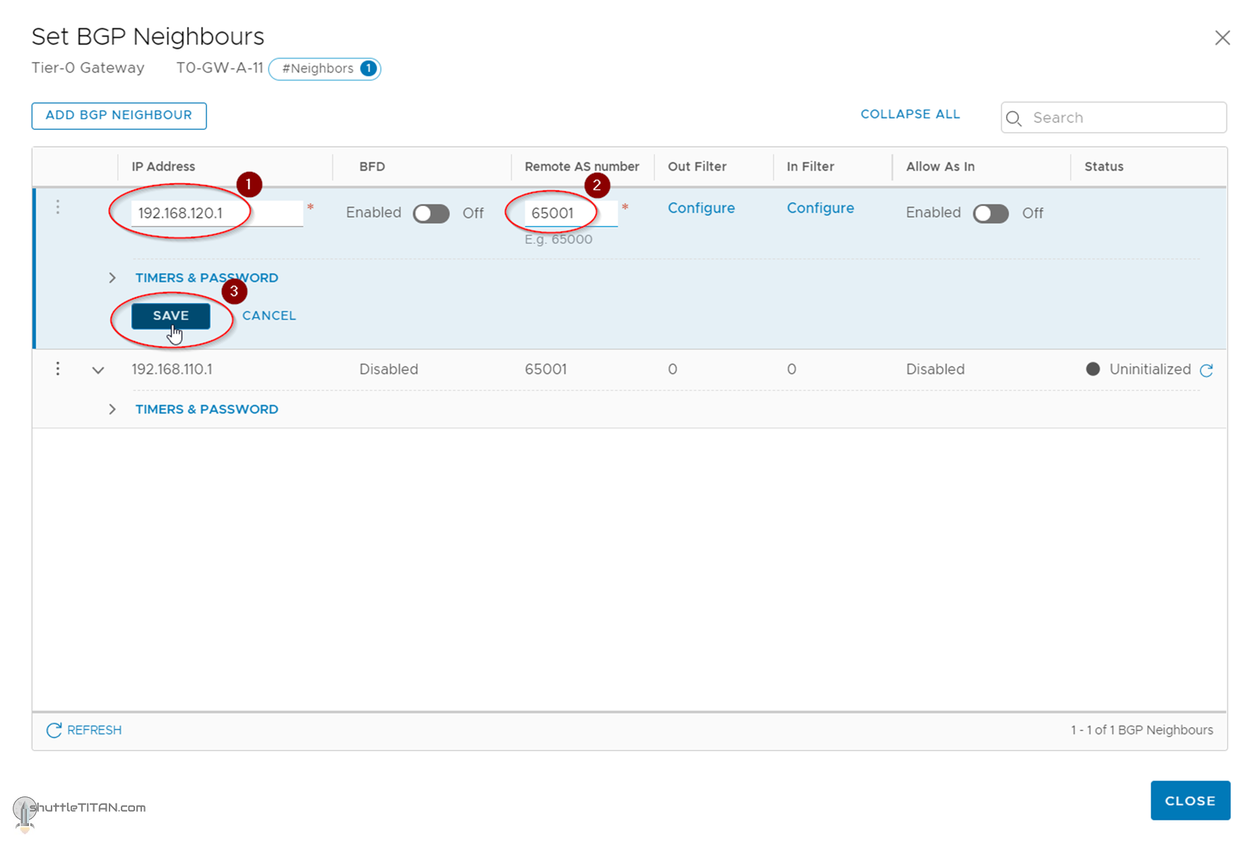
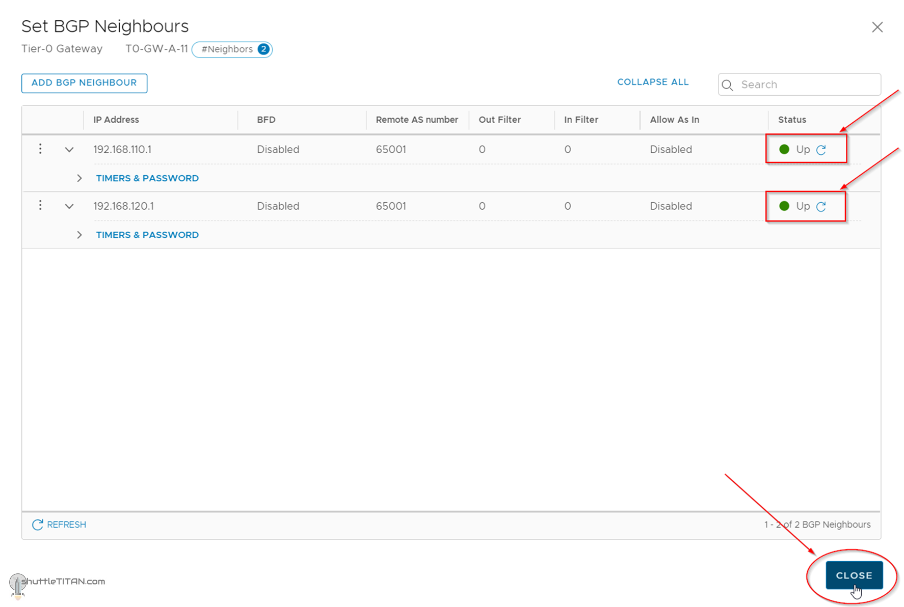
13. Specify the second neighbour interface, Remote AS number, Click “SAVE”:
14. Confirm the status as “Up”, Click “CLOSE”:
15. Click “CLOSE EDITNIG”:
Confirm the status showing “Up”, as shown in the screenshot below:
This concludes this step of creating T1 (Tier-0) Gateway, configuring BGP and its neighbors successfully.
Note: The scope of this NSX-T Installation series is only to configure one (1) interface per edge node for this “Active-Active” Tier-0 Gateway.
By default, Tier-0 tries to establish BGP neighbor on all External (Uplink) interfaces available. However, if you have two(2) ToR physical switches and would prefer to have two interfaces per edge node, you would need to map the BGP neighbor to use specific Uplink (External) Interface which is done via “Advanced UI”, discussed in the next blog in this series Step 18 – T0 (Tier-0) Gateway: Map BGP Neighbor to specific Uplink Interface.
We use cookies on our website to give you the most relevant experience by remembering your preferences and repeat visits. By clicking “Accept”, you consent to the use of ALL the cookies.
This website uses cookies to improve your experience while you navigate through the website. Out of these cookies, the cookies that are categorized as necessary are stored on your browser as they are essential for the working of basic functionalities of the website. We also use third-party cookies that help us analyze and understand how you use this website. These cookies will be stored in your browser only with your consent. You also have the option to opt-out of these cookies. But opting out of some of these cookies may have an effect on your browsing experience.
Necessary cookies are absolutely essential for the website to function properly. This category only includes cookies that ensures basic functionalities and security features of the website. These cookies do not store any personal information.
Any cookies that may not be particularly necessary for the website to function and is used specifically to collect user personal data via analytics, ads, other embedded contents are termed as non-necessary cookies. It is mandatory to procure user consent prior to running these cookies on your website.