If you have successfully followed all steps 1 – 12 of this NSX-T Installation series – Congratulations! you have now completed the setup of all components i.e. NSX-T Management Cluster, Host and Edge Transport Nodes. Your efforts of spending valuable time in getting your hands dirty with NSX-T Datacenter are commendable! From here on, we will dive into the Second Phase, focusing on building logical network topology that I alluded to in Step 0 – High Level Design.
Links to all the steps of the Second Phase for quick jump:
- Step 13 – Create T1 (Tier-1) Gateway – this blog
- Step 14 – Create Overlay Segments
- Step 15 (Option 1) – Migrate VM(s) from vDS to N-VDS
- Step 15 (Option 2) – Bulk VM Migration from vDS to N-VDS
- Step 16 – Create VLAN Segments
- Step 17 – Create T0 (Tier-0) Gateway [active-active] and configure BGP
- Step 18 – T0 (Tier-0) Gateway: Map BGP Neighbor to specific Uplink Interface
- Step 19 – Connect T1 (Tier-1) Gateway to T0 (Tier-0) Gateway
- Step 20 – Configure Route Distribution on T0 (Tier-0) Gateway
The previous step, discussed Edge Clusters, its scaling limitations and step-by-step instructions on how to configure one. This blog begins the Second Phase i.e. building the logical network topology and “Step 13” of this NSX-T Installation series, which will discuss T1 (Tier-1) Gateway, its considerations, SR (Service Router), DR (Distributed Router), followed by step-by-step instructions on how to create one.
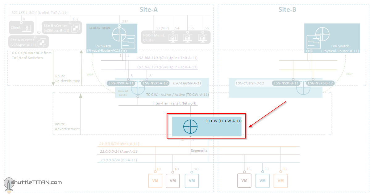
The image below highlights the logical entity of the “Routing Design” this step focuses on:
——————————————————————————————————————————————————
But before we proceed, I would encourage you to briefly skim through my other blogs below, which you may find useful for this step:
- NSX-T Architecture (Revamped)for v2.4 and later
- Series Overview: Step 0 – High Level Design
It is assumed that you have NSX-T Management Cluster deployed, Host and Edge Transport Nodes configured and ready to use. If not, please refer the steps 1 to 12 in this NSX-T Installation series for guidance.
If you are deploying this in your home lab or performing a PoC in a nested vSphere Environment, I would also suggest you have a quick glance of my blog Home Lab Setup – Nested ESXi Host’s networking for NSX-T.
——————————————————————————————————————————————————
A Tier-1 Gateway performs the functions of a tier-1 logical router. It has downlink connections to segment and uplink connections (auto-plumb) to a tier-0 gateway. The auto-plumbing from a Tier-1 Gateway supports Route Advertisements, static and recursive static routes.
NSX-T v2.4 introduced quite a lot of changes, one of them was the new UI i.e. introduction of the “Simplified UI” (also known as Policy UI) and “Advance UI” (also known as Manager UI). If you are familiar with the previous versions of NSX-T (v2.3 and before), the “Tier-1 Router” is now referred to as “Tier-1 Gateway” in the new “Simplified UI” but is referred to as Tier-1 logical router in the “Advance UI“.
Background: Each logical router contains a services router (SR) and a distributed router (DR). A DR is distributed across all transport nodes that belong to the same transport zone and an SR is centrally instantiated on the Edge Appliance(s). An SR instance is required for services that cannot be distributed i.e. Physical Connectivity, NAT, DHCP, Load Balancers, etc.
- A DR component for the Tier-1 Gateway is instantiated on the Transport Nodes when a segment is connected to the Tier-1 Gateway providing East-West routing.
- While an SR component for the Tier-1 Gateway is instantiated on the Edge Nodes when it is configured with DNAT, Edge firewall, or a load balancer.
- Auto Plumbing of T1 SR to T0 DR is done by “Inter-Tier” LS/Segment (VNI 65549) using 100.64 subnet (reserved)
- Auto Plumbing of DR to SR is done by “Transit Segment” LS/Segment (VNI 69639) using 169.254 subnet (reserved)
Tier-1 Gateway Considerations:
- The traffic to and from another tier-1 logical router is processed in this order: DNAT first, then Edge firewall, and then load balancer.
- The Traffic within the Tier-1 logical router is processed through DNAT first and then load balancer; edge firewall processing is skipped.
- If the Tier-1 Gateway is used for only East-West routing, then it should not be connected to the Tier-0 router otherwise the traffic trombones via Edge nodes.
- A Tier-1 Gateway do not have the functionality for providing Physical Connectivity which is done by a Tier-0 Router (will be discussed in Step 17 – Create T0 (Tier-0) Gateway [active-active] and Configure BGP)
- Load balancers are only supported on a Tier-1 router
If you would like to further deep dive in NSX-T routing, please see this blog by Amit Aneja.
With that lets get started…
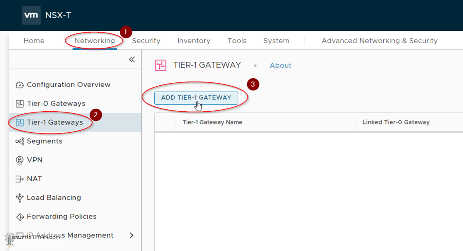
1. Click Networking -> Tier-1 Gateways -> ADD TIER-1 GATEWAY
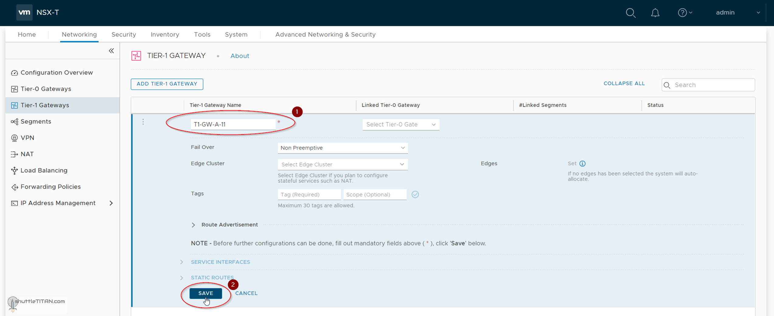
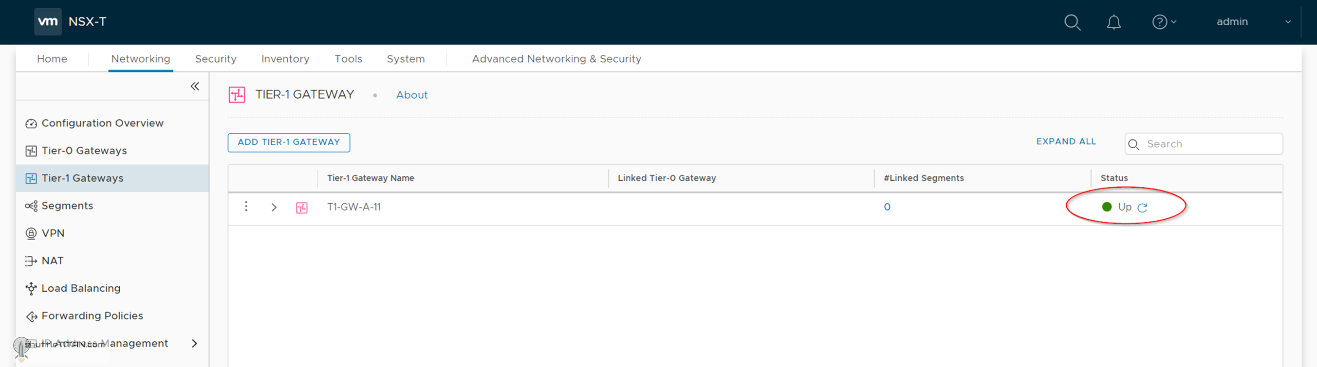
2. Specify the name as “T1-GW-A-11” and leave all other settings default, Click SAVE:
Note: At this point we are not linking the Tier-1 Gateway to a Tier-0 Gateway. It will be linked in Step 19 – Connect T1 (Tier-1) Gateway to T0 (Tier-0) Gateway.
3. Click “No” when asked to continue configuring the Tier-1 Gateway:
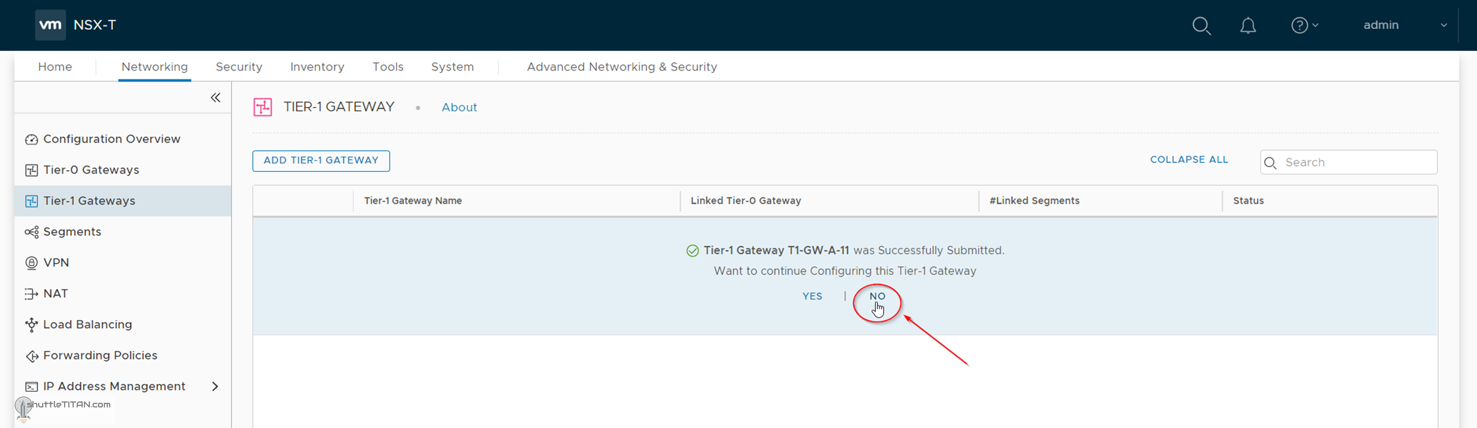
Confirm the status, it should show “Up” when the Tier 1 Gateway is ready for use:
This concludes the short step of creating an NSX-T Tier-1 Gateway successfully.
Let’s proceed ahead with the next blog in this series Step 14 – Create Overlay Segments.