The steps 1 to 12 of this NSX-T Installation series focused on the setup of the NSX-T Datacenter components i.e. NSX-T Management Cluster, Host and Edge Transport Nodes. From, Step 13 onwards, the focus shifted to building logical network topology that I alluded to in Step 0 – High Level Design.
Links to all the steps of the Second Phase for quick jump:
- Step 13 – Create T1 (Tier-1) Gateway
- Step 14 – Create Overlay Segments
- Step 15 (Option 1) – Migrate VM(s) from vDS to N-VDS
- Step 15 (Option 2) – Bulk VM Migration from vDS to N-VDS
- Step 16 – Create VLAN Segments
- Step 17 – Create T0 (Tier-0) Gateway [active-active] and configure BGP
- Step 18 – T0 (Tier-0) Gateway: Map BGP Neighbor to specific Uplink Interface – this blog
- Step 19 – Connect T1 (Tier-1) Gateway to T0 (Tier-0) Gateway
- Step 20 – Configure Route Distribution on T0 (Tier-0) Gateway
The previous step, discussed T0 (Tier-0) Gateway, its considerations, SR (Service Router), DR (Distributed Router), followed by step-by-step instructions on how to create an active-active T0 Gateway. This blog is part of the Second Phase i.e. building the logical network topology and “Step 18” of the NSX-T Installation series, in which we will discuss “Why” we need to map BGP Neighbor to specific Uplink (External) Interfaces, step-by-step instructions on how to map and validate via command line.
——————————————————————————————————————————————————
But before we proceed, I would encourage you to briefly skim through my other blogs below, which you may find useful for this step:
- NSX-T Architecture (Revamped)for v2.4 and later
- Series Overview: Step 0 – High Level Design
- Preceding Step (Pre-requisites): Step 17 – Create T0 (Tier-0) Gateway [active-active] and Configure BGP Neighbors
It is assumed that you have NSX-T Management Cluster deployed, Host and Edge Transport Nodes configured and ready to use. If not, please refer the steps 1 to 12 in this NSX-T Installation series for guidance.
If you are deploying this in your home lab or performing a PoC in a nested vSphere Environment, I would also suggest you have a quick glance of my blog Home Lab Setup – Nested ESXi Host’s networking for NSX-T.
——————————————————————————————————————————————————–
OK, the Question “Why” this step?
By default, Tier-0 tries to establish BGP neighbor on all External (Uplink) interfaces available. If you have two(2) ToR physical switches and would prefer to have two interfaces per edge node, you would need to map the BGP neighbor to use specific Uplink (External) Interface which is done via “Advanced UI”.
Note: NSX-T v2.4 introduced quite a lot of changes, one of them was the new UI i.e. introduction of the “Simplified UI” (also known as Policy UI) and “Advance UI” (also known as Manager UI). If you are familiar with the previous versions of NSX-T (v2.3 and before), the “Tier-0 Router” is now referred to as “Tier-0 Gateway” in the new “Simplified UI” but is referred to as “Tier-0 logical router” in the “Advance UI“.
With that lets get started…
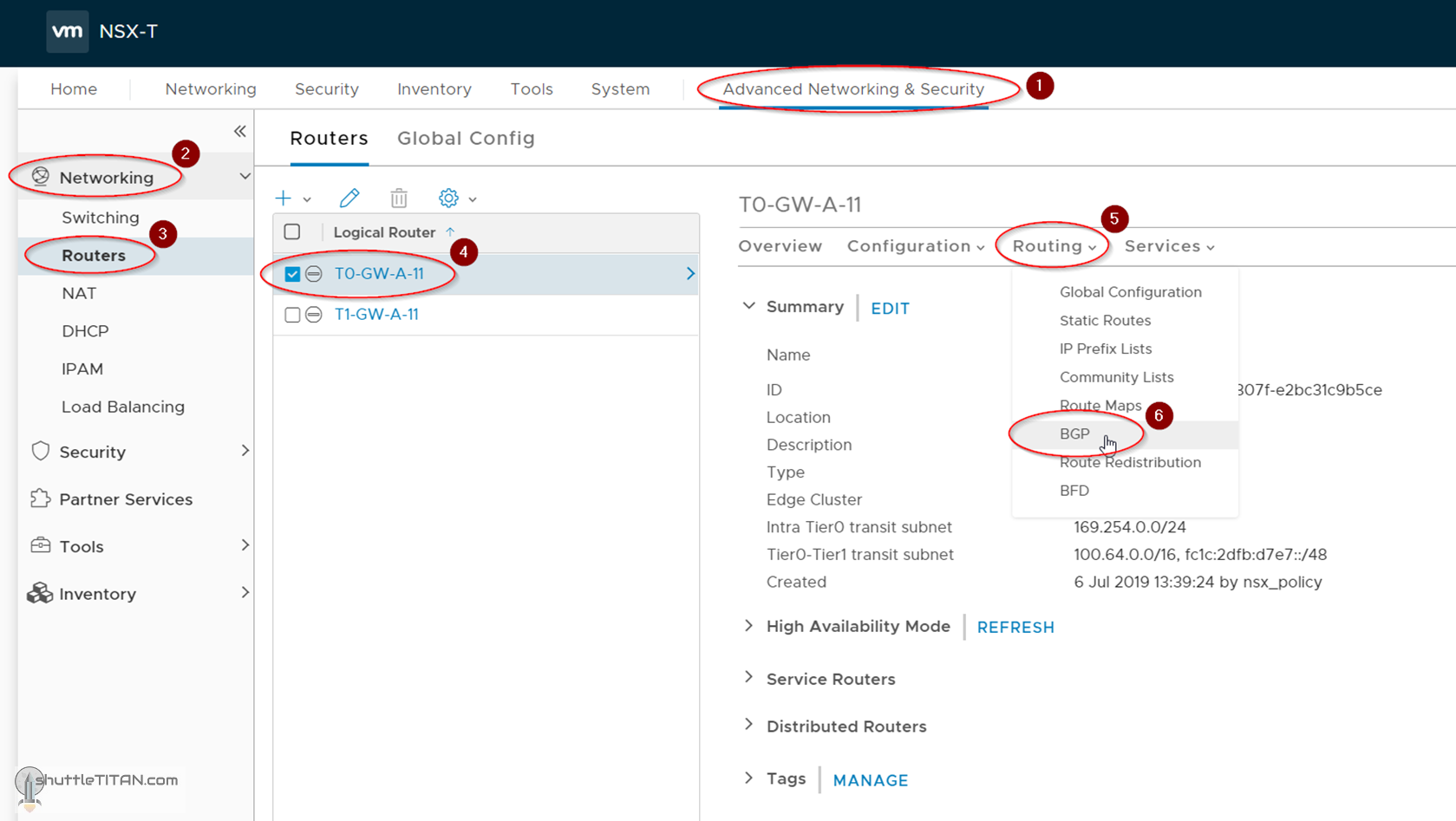
1. Click “Advanced Networking & Security” -> Networking -> Routers -> Click the T0 Gateway i.e. T0-GW-A-11 (created in the previous step) -> Routing -> BGP:
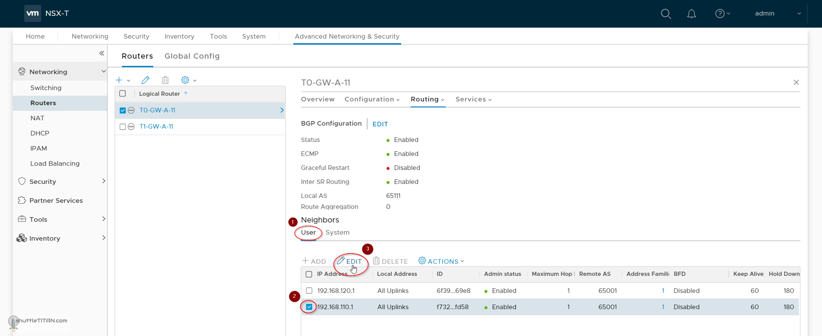
2. Click User -> Select the first Neighbor IP i.e. 192.168.110.1 -> click “EDIT”:
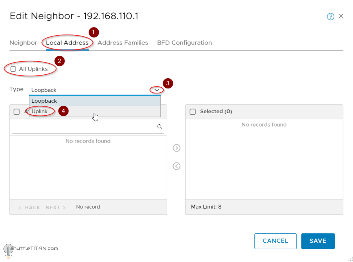
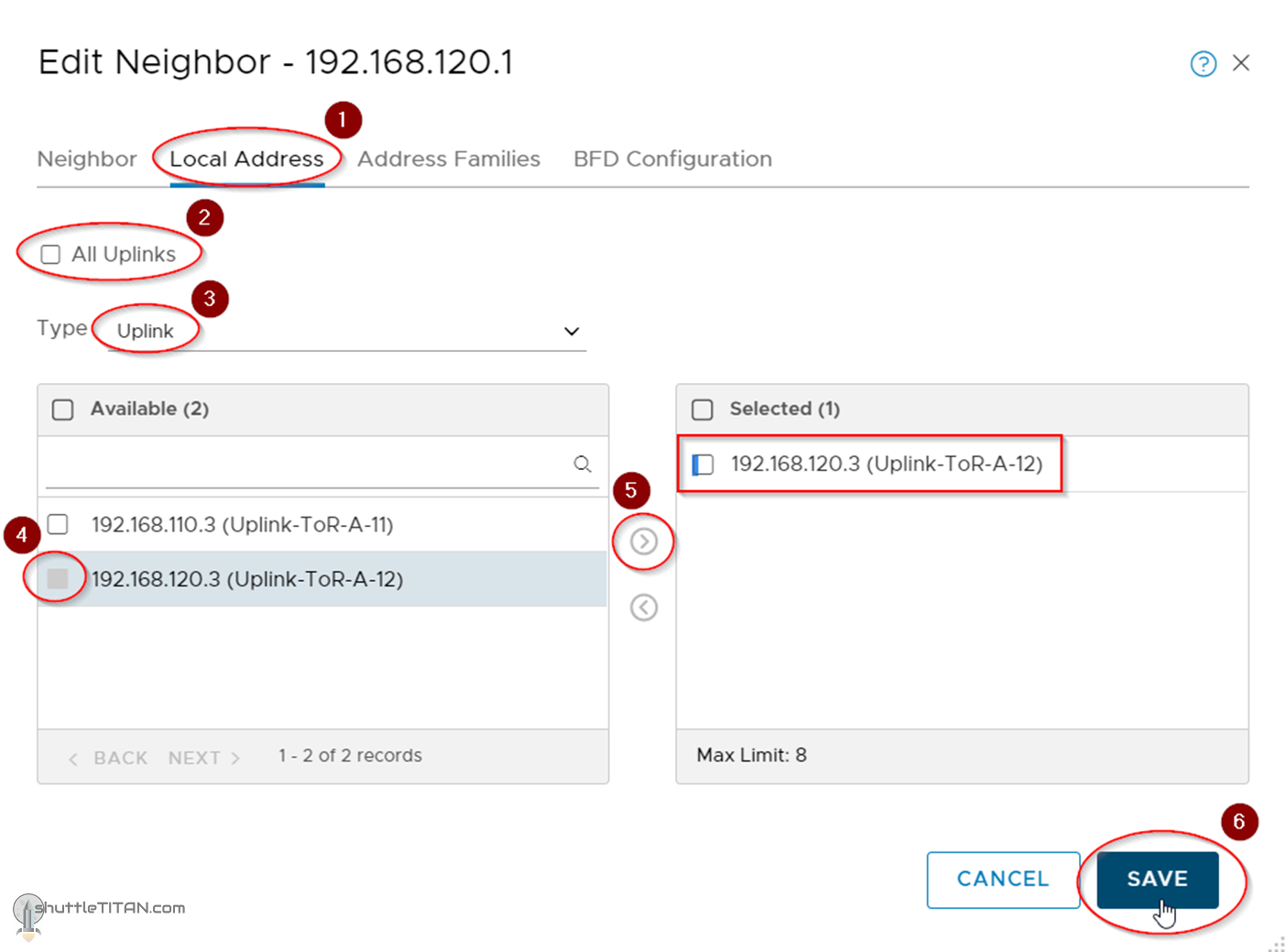
3. Click Local Address -> Uncheck “All Uplinks” -> Select Uplink from the dropdown menu:
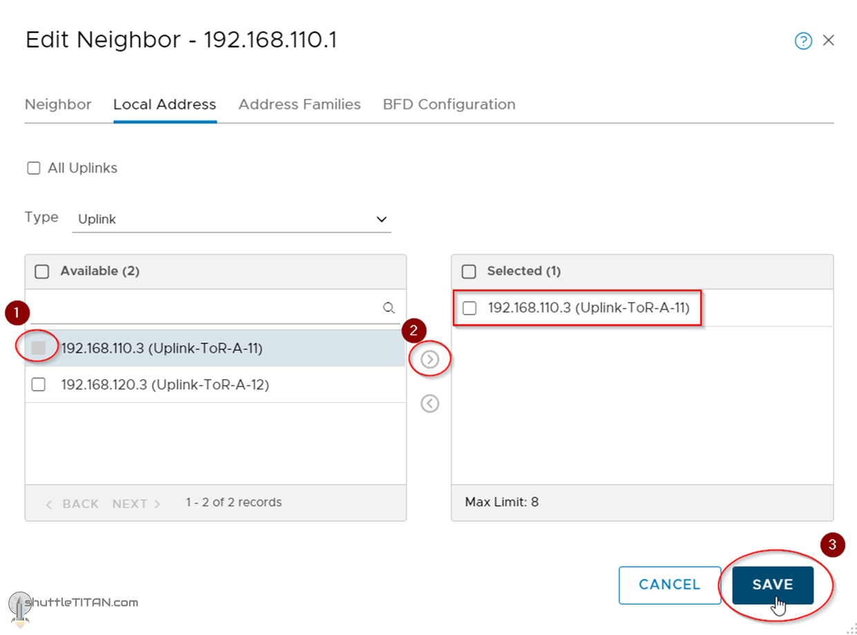
4. Select the Appropriate Uplink i.e. 192.168.110.3 (Uplink-ToR-A-11) and click “SAVE”:
5. Follow the same steps to map the second neighbor 192.168.120.1 to 192.168.120.3 (Uplink-ToR-A-12):
Let’s validate the BGP neighbour establishment via the command line:
- Logon to one of the Edge Nodes as “admin”
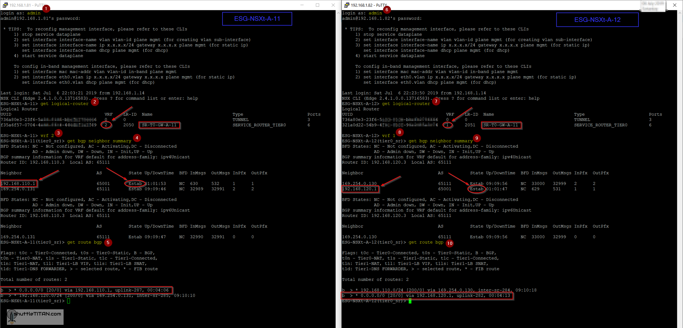
- Run the following command to list all logical routers:
get logical-router
Identify the T0-GW-A-11 Service Router’s VRF number, in my case it was “2”
- Run the command vrf <number> :
vrf 2
- Next run the following command to show all bgp neighbour;s summary:
get bgp neighbor summary
Note: The BGP neighbour 192.168.110.1 state shows Established
- To List all learnt routes, run the following command:
get route bgp
- The output will now show the default route being learnt from the BGP neighbour 192.168.110.1
Follow the same steps on the second Edge Node as shown in the screenshot below:
This concludes this step to map BGP neighbors to specific Uplinks and validate the configuration via command line successfully.
Let’s proceed ahead with the next blog in this series Step 19 – Connect T1 (Tier-1) Gateway to T0 (Tier-0) Gateway.