The steps 1 to 12 of this NSX-T Installation series focused on the setup of the NSX-T Datacenter components i.e. NSX-T Management Cluster, Host and Edge Transport Nodes. From, Step 13 onwards, the focus shifted to building logical network topology that I alluded to in Step 0 – High Level Design.
Links to all the steps of the Second Phase for quick jump:
- Step 13 – Create T1 (Tier-1) Gateway
- Step 14 – Create Overlay Segments
- Step 15 (Option 1) – Migrate VM(s) from vDS to N-VDS
- Step 15 (Option 2) – Bulk VM Migration from vDS to N-VDS
- Step 16 – Create VLAN Segments – this blog
- Step 17 – Create T0 (Tier-0) Gateway [active-active] and configure BGP
- Step 18 – T0 (Tier-0) Gateway: Map BGP Neighbor to specific Uplink Interface
- Step 19 – Connect T1 (Tier-1) Gateway to T0 (Tier-0) Gateway
- Step 20 – Configure Route Distribution on T0 (Tier-0) Gateway
The previous step, discussed step-by-step instructions on how to migrate VM(s) from vDS to N-VDS. This blog is part of the “Second Phase” i.e. building the logical network topology and “Step 16” of the NSX-T Installation series, in which we will discuss VLAN Segments and step-by-step instructions on how to configure one.
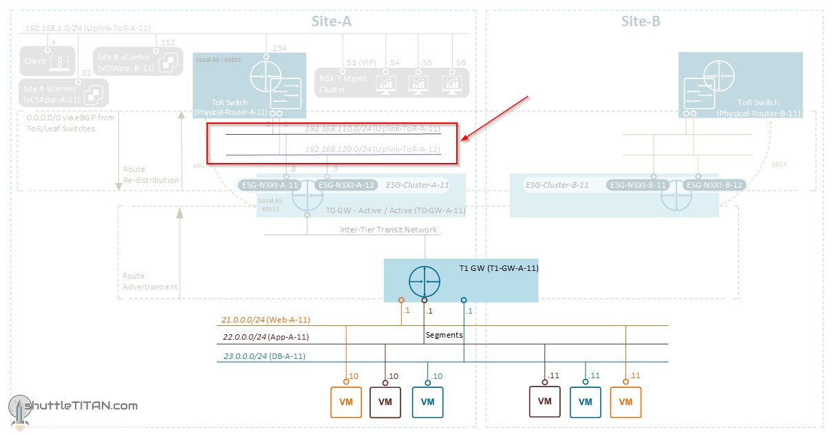
The image below highlights the logical entity of the “Routing Design” this step focuses on:
——————————————————————————————————————————————————
Before we proceed, I would encourage you to briefly skim through my other blogs below, which you may find useful for this step:
- NSX-T Architecture (Revamped)for v2.4 and later
- Series Overview: Step 0 – High Level Design
It is assumed that you have NSX-T Management Cluster deployed, Host and Edge Transport Nodes configured and ready to use. If not, please refer the steps 1 to 12 in this NSX-T Installation series for guidance.
If you are deploying this in your home lab or performing a PoC in a nested vSphere Environment, I would also suggest you have a quick glance of my blog Home Lab Setup – Nested ESXi Host’s networking for NSX-T.
——————————————————————————————————————————————————
We created Overlay segments in Step 14 and just to refresh your memory, I have copy/paste the snippet from that step, to provide an quick overview on Segments:
**************************************************
A Segment performs the functions of a logical switch and connects to gateways and VMs. Like the Tier-1 Gateway, a Segment has different naming references: “Segment” in the Simplified UI (Policy UI) and logical switch in the Advance UI (Manager UI).
Depending upon the “Transport Zone” (selected while creating a segment), a vLAN or Overlay segment is instantiated.
Note: An N-VDS switch configured in the Enhanced Datapath mode supports IP Discovery, SpoofGuard and IPFIX profiles.
**************************************************
With that lets get started…
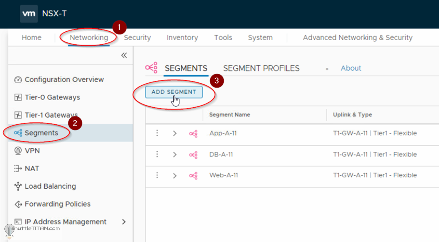
1. Click Networking -> Segments -> ADD SEGMENT:
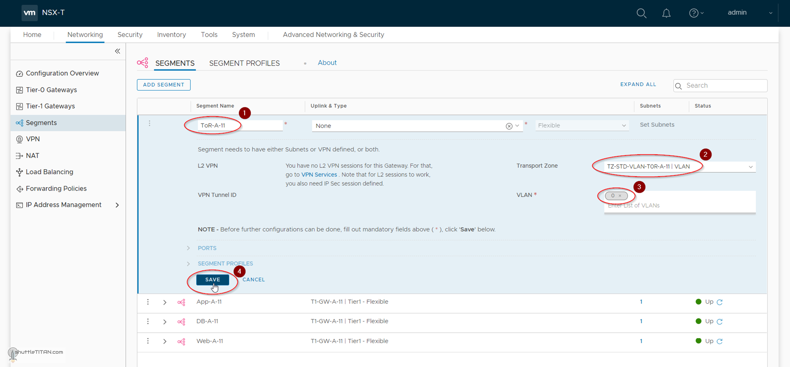
2. Specify the name as ToR-A-11, select the Transport Zone as TZ-STD-VLAN-TOR-A-11 (created in Step – 6), specify the vLAN (if any) and click Save:
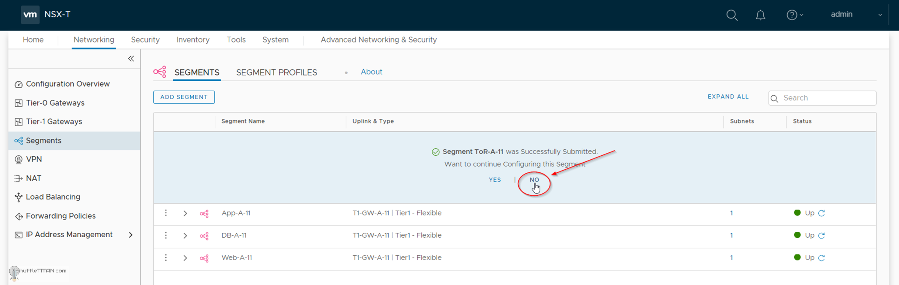
3. Click “No”, when prompted for continuing to configure the segment:
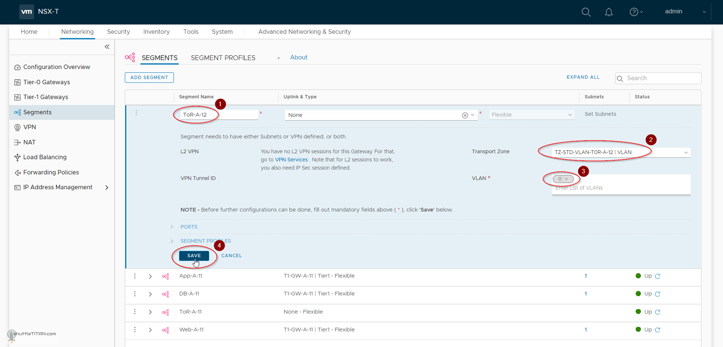
Follow the same steps again to create ToR-A-12 segment using transport Zone as TZ-STD-VLAN-TOR-A-12 (created in Step – 6) as shown in the screenshot below:
Unlike Overlay Segments created in Step 14, there will be no change in the visualization on the vCenter N-VDS, as the VLAN transport zone used in this step are only used by the Edge Transport Nodes.
This concludes this step of creating VLAN segments successfully.
Let’s proceed ahead with the next blog in this series Step 17 – Create T0 (Tier-0) Gateway [active-active] and configure BGP.