The steps 1 to 12 of this NSX-T Installation series focused on the setup of the NSX-T Datacenter components i.e. NSX-T Management Cluster, Host and Edge Transport Nodes. From, Step 13 onwards, the focus shifted to building the logical network topology that I alluded to in Step 0 – High Level Design.
Links to all the steps of the Second Phase for quick jump:
The previous step, discussed T1 (Tier-1) Gateway, its considerations, SR (Service Router), DR (Distributed Router), followed by step-by-step instructions on how to create one. This blog is part of the Second Phase i.e. building the logical network topology and “Step 14” of the NSX-T Installation series, where we will discuss Overlay Segments and step-by-step instructions on how to configure one.
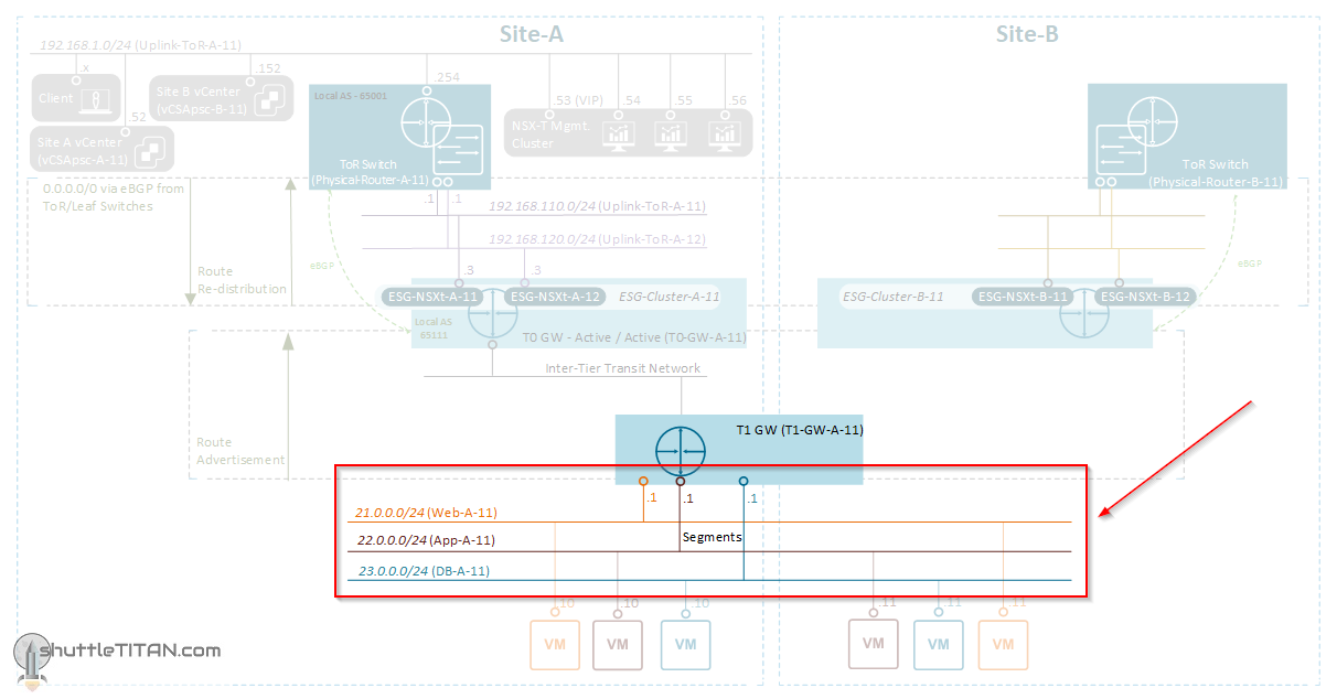
The image below highlights the logical entity of the “Routing Design” this step focuses on:
—————————————————————————————————————————————————— But before we proceed, I would encourage you to briefly skim through my other blogs below, which you may find useful for this step:
It is assumed that you have NSX-T Management Cluster deployed, Host and Edge Transport Nodes configured and ready to use. If not, please refer the steps 1 to 12 in this NSX-T Installation series for guidance.
If you are deploying this in your home lab or performing a PoC in a nested vSphere Environment, I would also suggest you have a quick glance of my blog Home Lab Setup – Nested ESXi Host’s networking for NSX-T. ——————————————————————————————————————————————————–
A Segment performs the functions of a logical switch and connects to gateways and VMs. Like the Tier-1 Gateway, a Segment has different naming references: “Segment” in the Simplified UI (Policy UI) and logical switch in the Advance UI (Manager UI).
Depending upon the “Transport Zone” (selected while creating a segment), a vLAN or Overlay segment is instantiated.
Note: An N-VDS switch configured in the Enhanced Datapath mode supports IP Discovery, SpoofGuard and IPFIX profiles.
With that lets get started…
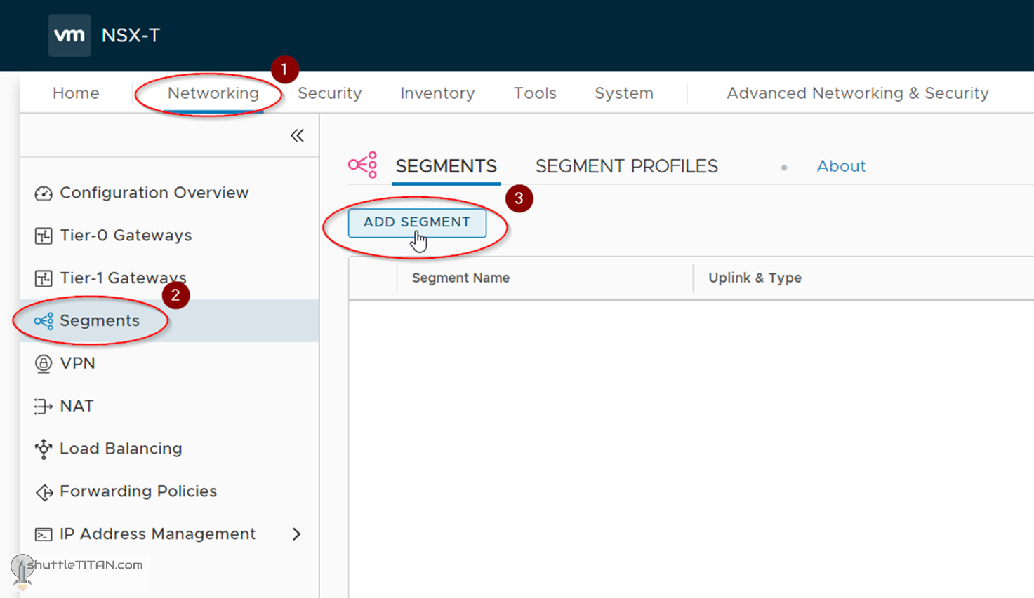
1. Click Networking -> Segments -> ADD SEGMENT:
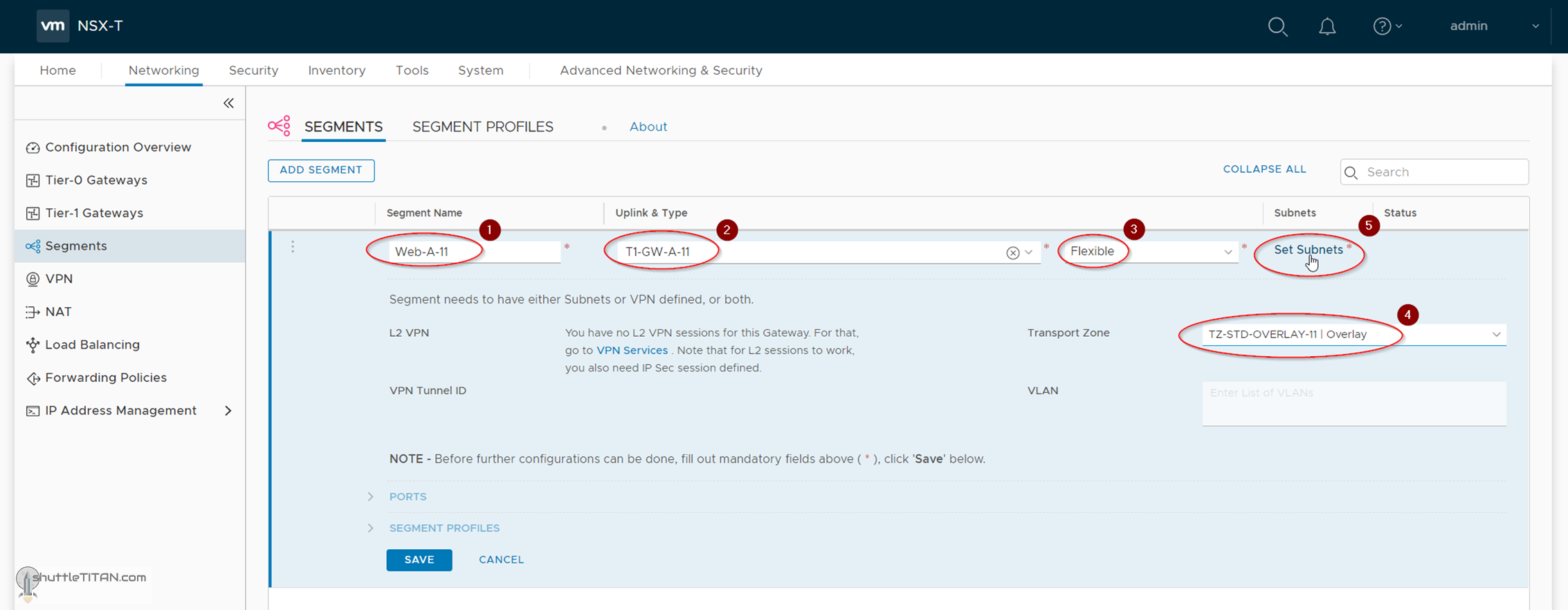
2. Specify the name as Web-A-11, Uplink as T1-GW-A-11 (created in previous step), select the Transport Zone as TZ-STD-OVERLAY-11 (created in Step – 6) and click “Set-Subnets”:
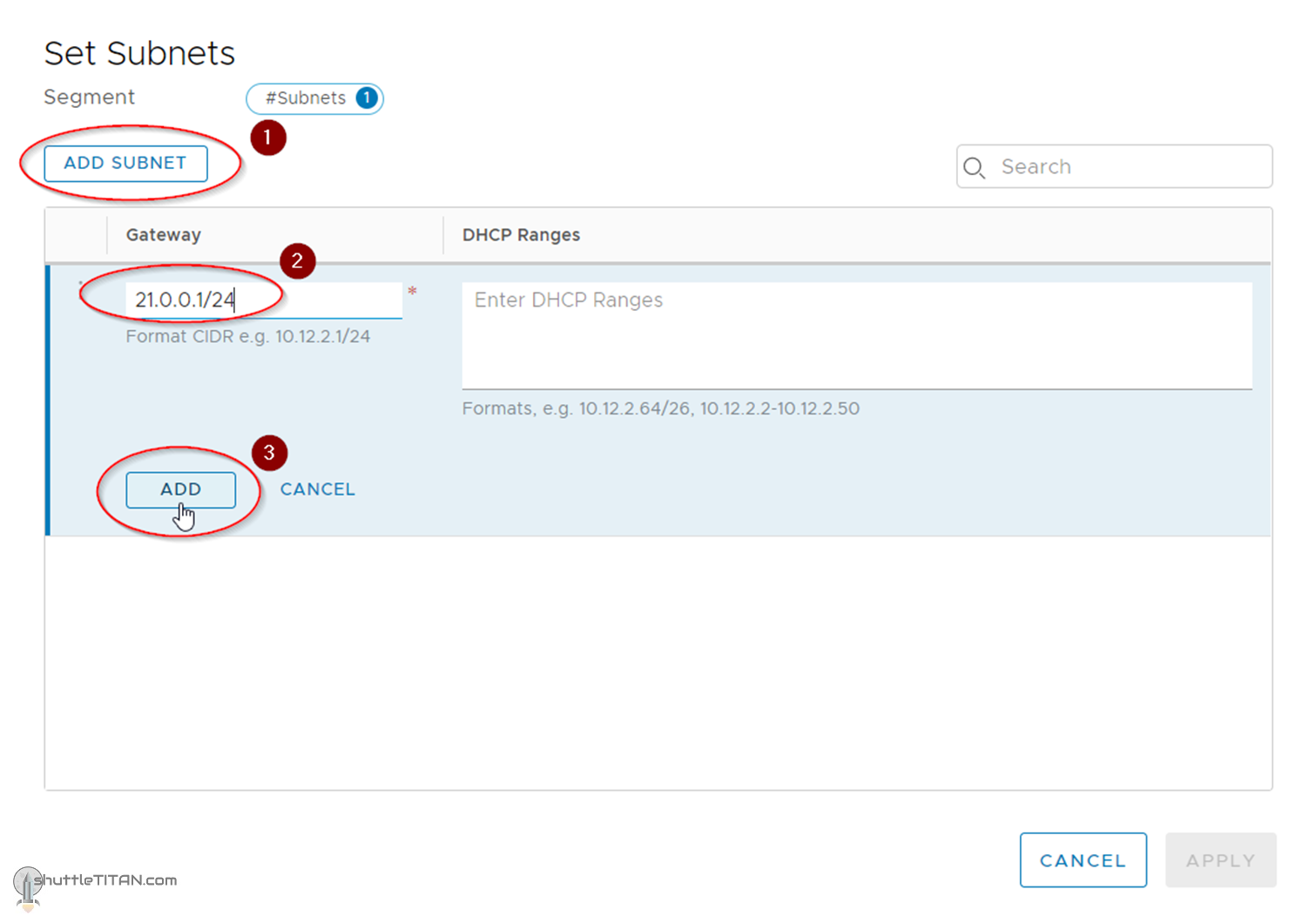
3. Click ADD SUBNET -> Specify the Gateway as 21.0.0.1/24 and click “ADD”:
4. Click “Apply”:
5. Click Save:
6. Click “No”, when prompted for continuing to configure the segment:
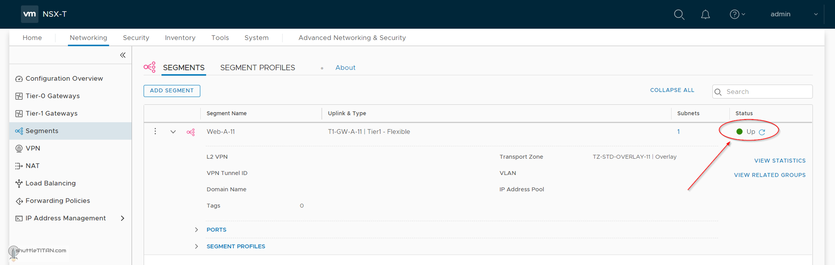
7. Confirm the status showing “Up”, as shown in the screenshot below:
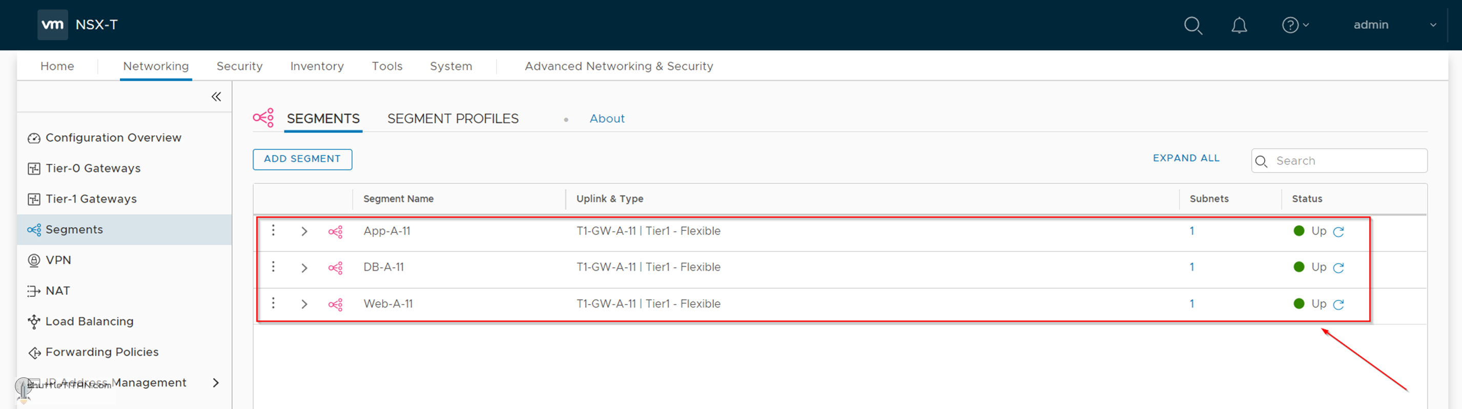
Follow the same steps to create APP-A-11 and DB-A-11, as shown in the screenshot below:
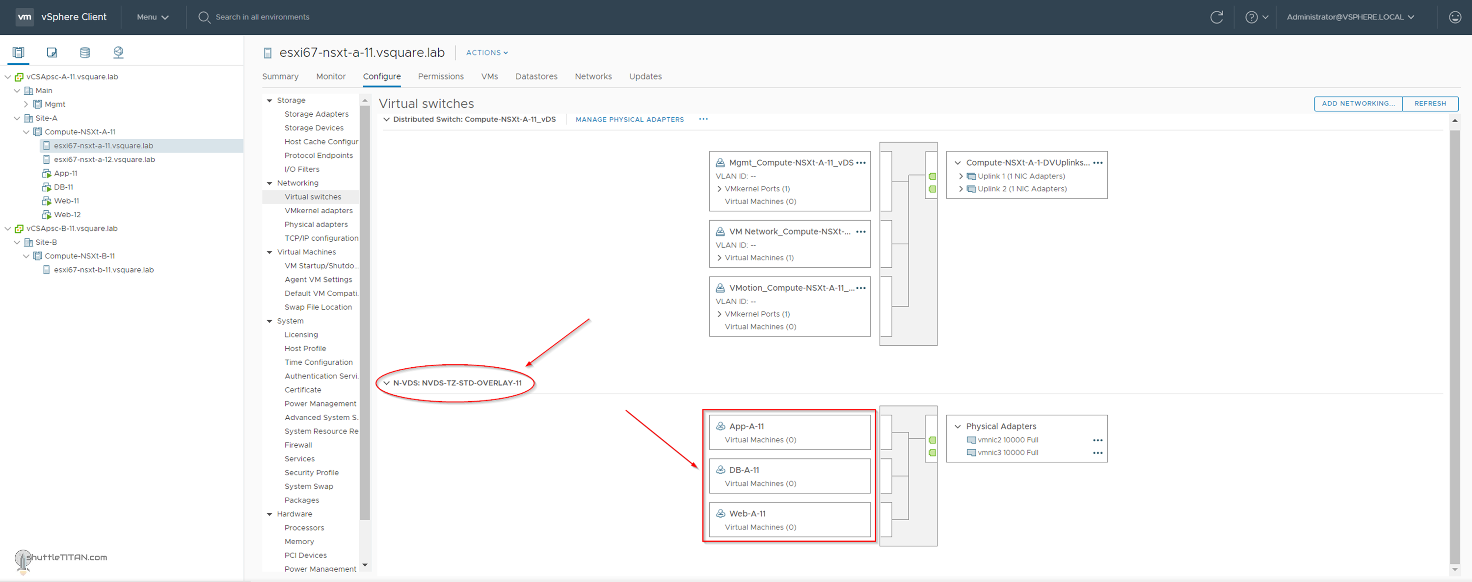
You could also logon to the vCenter to visualize the segments just created:
This concludes this step of creating overlay segments successfully.
We use cookies on our website to give you the most relevant experience by remembering your preferences and repeat visits. By clicking “Accept”, you consent to the use of ALL the cookies.
This website uses cookies to improve your experience while you navigate through the website. Out of these cookies, the cookies that are categorized as necessary are stored on your browser as they are essential for the working of basic functionalities of the website. We also use third-party cookies that help us analyze and understand how you use this website. These cookies will be stored in your browser only with your consent. You also have the option to opt-out of these cookies. But opting out of some of these cookies may have an effect on your browsing experience.
Necessary cookies are absolutely essential for the website to function properly. This category only includes cookies that ensures basic functionalities and security features of the website. These cookies do not store any personal information.
Any cookies that may not be particularly necessary for the website to function and is used specifically to collect user personal data via analytics, ads, other embedded contents are termed as non-necessary cookies. It is mandatory to procure user consent prior to running these cookies on your website.