The previous step, discussed NSX-T Edge nodes and step-by-step instructions on how to install NSX Edge VM on ESXi using vSphere UI. This blog is the “Step 11” of the NSX-T Installation series, where we will discuss Edge Transport Nodes, its networking design and step-by-step instructions on how to configure one.
————————————————————————————————————————————————————— But before we proceed, I would encourage you to briefly skim through my other blogs below, which you may find useful for this step:
If you are deploying this in your home lab or performing a PoC in a nested vSphere Environment, I would also suggest you have a quick glance of my blog Home Lab Setup – Nested ESXi Host’s networking for NSX-T. ——————————————————————————————————————————————————————
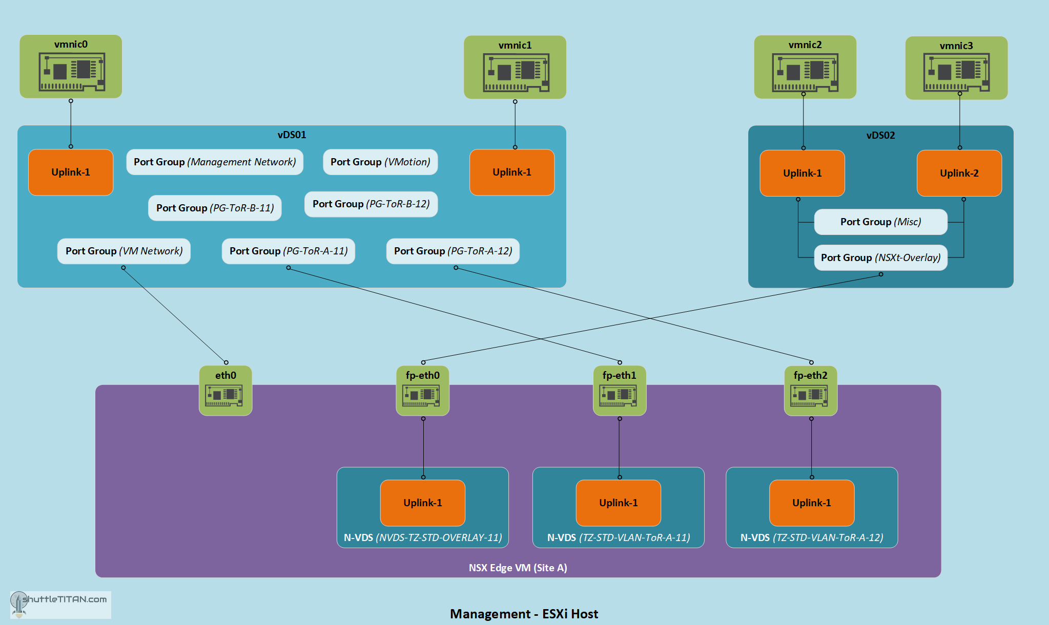
If your ESXi Hosts (in the Management/Edge vSphere cluster have 4 pnics) and physical Compute ESXi hosts, the NSX-T Edge uplink design may look like below:
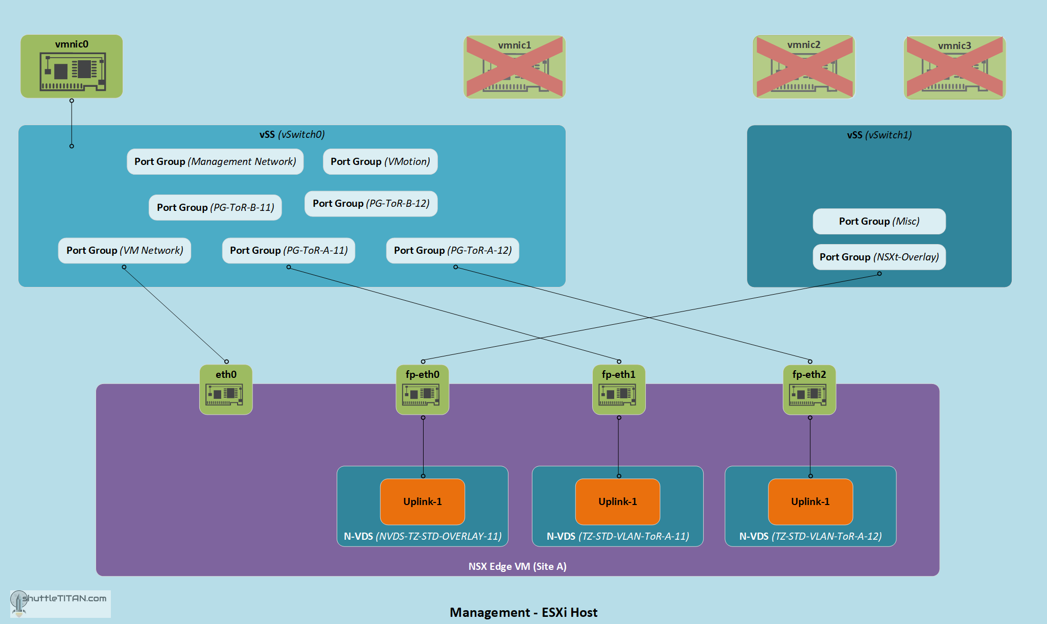
However, if you are deploying this in a Home Lab or performing a PoC, following my blog Home Lab Setup – Nested ESXi Host’s networking for NSX-T, the NSX-T Edge design will look like below, as I am using only ONE pnic on my Management/Edge ESXi Host and all Compute ESXi hosts are nested:
With that let’s get started…
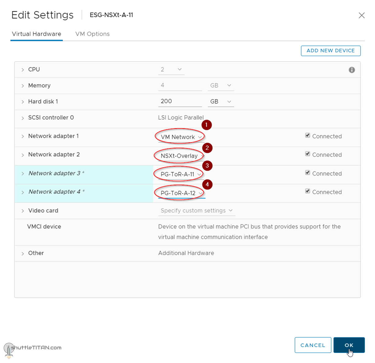
1. Edit the Edge VMs, deployed via vSphere UI in the previous step, configure the 4 vNICs as below:
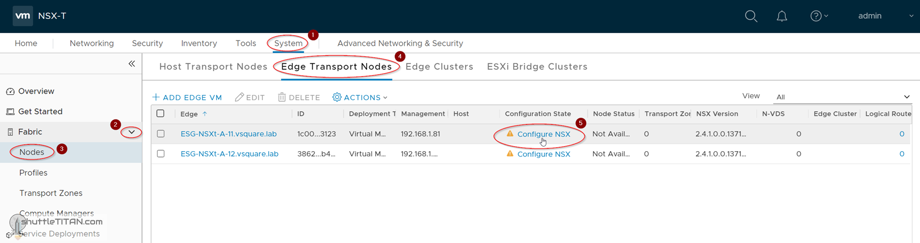
2. Click System -> Fabric -> Nodes -> Edge Transport Nodes -> Click Configure NSX:
3. Select the Overlay and the two ToR Transport Zones, Click N-VDS:
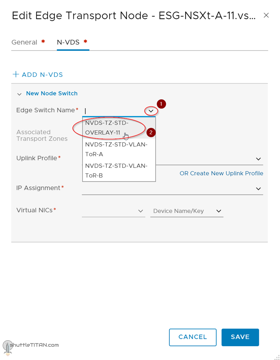
4. Select the Overlay N-VDS from the drop-down menu:
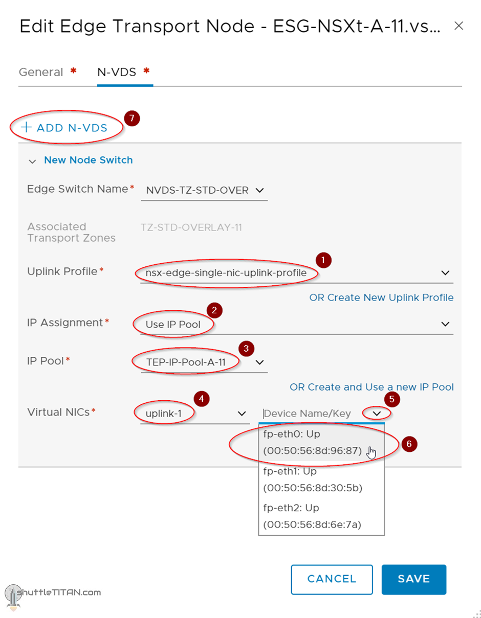
5. Select the uplink profile, IP Pool, Virtual NIC as “Uplink 1” and “fp-eth0”. Click “ADD N-VDS”, as shown in the screenshot below
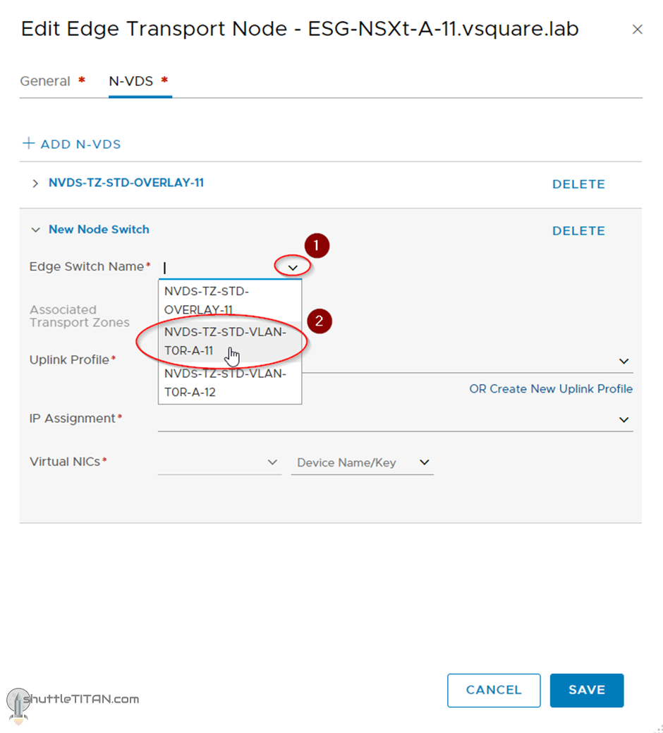
6. Select the first ToR N-VDS from the drop-down menu:
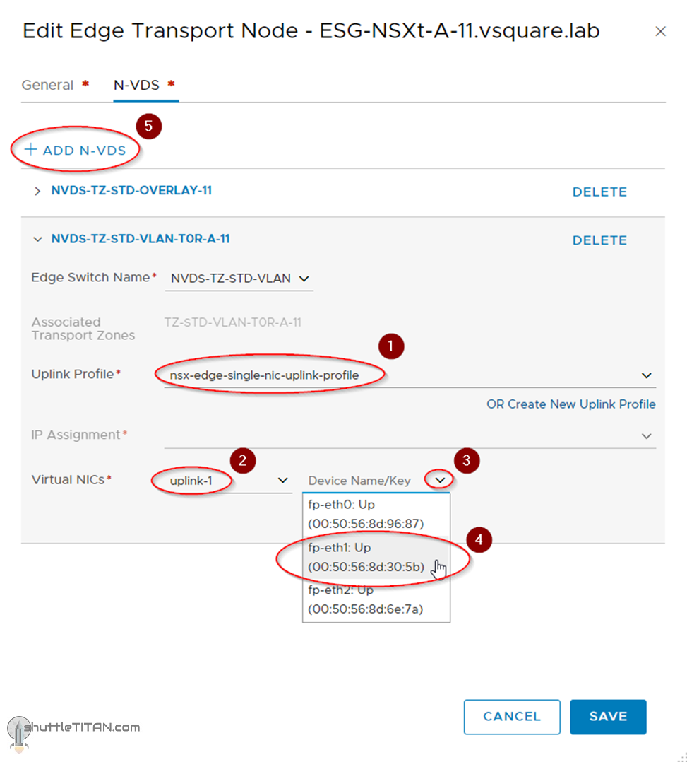
7. Select the uplink profile, Virtual NIC as “Uplink 1” and “fp-eth1”. Click “ADD N-VDS”, as shown in the screenshot below:
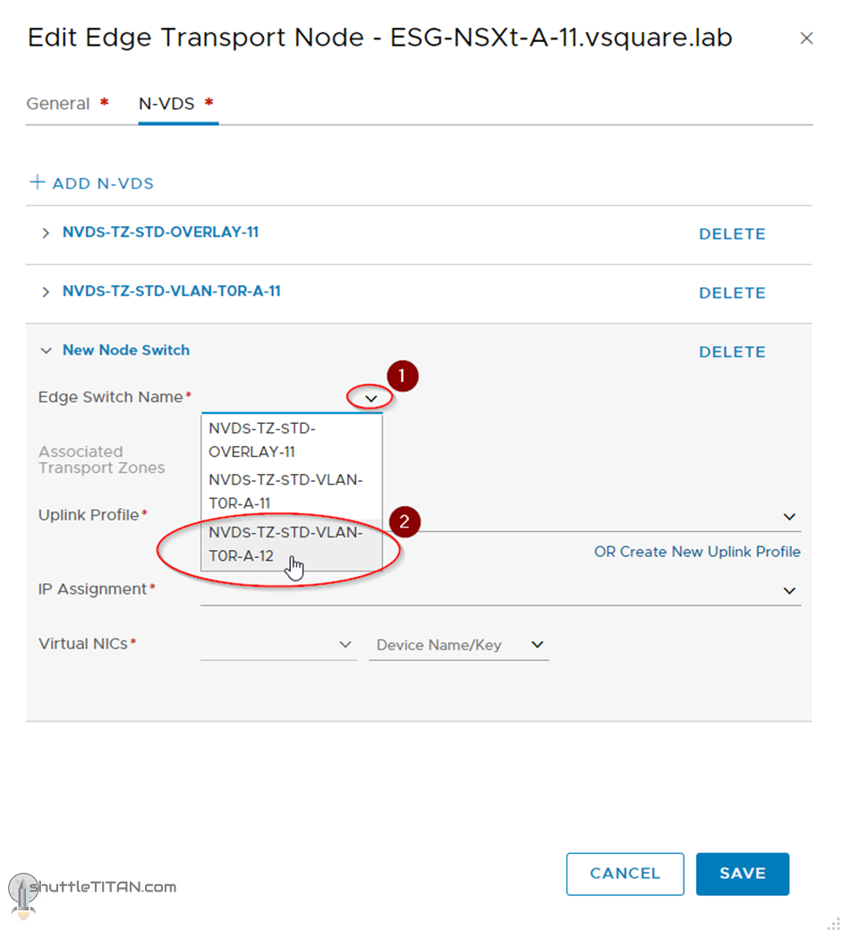
8. Select the second ToR N-VDS from the drop-down menu:
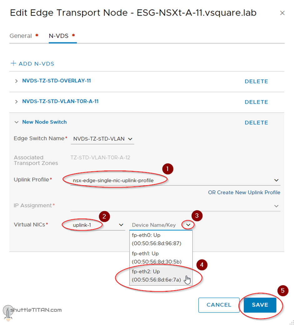
9. Select the uplink profile, Virtual NIC as “Uplink 1” and “fp-eth2”. Click “SAVE”, as shown in the screenshot below:
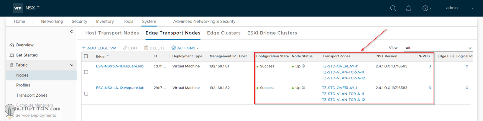
Follow the same steps for the Second ESG, by changing the “name” and “FQDN” as shown in the screenshot below:
This concludes this step of configuring Edge Transport Node successfully.
We use cookies on our website to give you the most relevant experience by remembering your preferences and repeat visits. By clicking “Accept”, you consent to the use of ALL the cookies.
This website uses cookies to improve your experience while you navigate through the website. Out of these cookies, the cookies that are categorized as necessary are stored on your browser as they are essential for the working of basic functionalities of the website. We also use third-party cookies that help us analyze and understand how you use this website. These cookies will be stored in your browser only with your consent. You also have the option to opt-out of these cookies. But opting out of some of these cookies may have an effect on your browsing experience.
Necessary cookies are absolutely essential for the website to function properly. This category only includes cookies that ensures basic functionalities and security features of the website. These cookies do not store any personal information.
Any cookies that may not be particularly necessary for the website to function and is used specifically to collect user personal data via analytics, ads, other embedded contents are termed as non-necessary cookies. It is mandatory to procure user consent prior to running these cookies on your website.