The previous step, discussed “what is an Uplink Profile”, Compute Host’s networking design, Uplink Profile for Edge VM consideration and finally the step-by-step instructions to create one. This blog is the “Step 8” of the NSX-T Installation series, where we will discuss Transport Node Profiles, its considerations and step-by-step instructions on how to create one.
—————————————————————————————————————————————————————
But before we proceed, I would encourage you to briefly skim through my other blogs below, which you may find useful for this step:
- NSX-T Architecture (Revamped)for v2.4 and later
- Series Overview: Step 0 – High Level Design
- Preceding Steps (Pre-requisites):
If you are deploying this in your home lab or performing a PoC in a nested vSphere Environment, I would also suggest you have a quick glance of my blog Home Lab Setup – Nested ESXi Host’s networking for NSX-T.
—————————————————————————————————————————————————————
Let’s begin with the question – What is an Transport Node Profile?
Transport node profile clubs an IP Pool, Transport Zone(s) and Uplink profile (discussed and created in the previous steps) in a single configuration profile that is applied to the Transport nodes e.g. hypervisors. It defines the network configuration of a transport node with N-VDS configuration, IP assignment and uplink to physical NIC mapping.
Transport node profile are applied to vSphere Cluster(s), in-order to propagate to multiple ESXi hosts and cannot be applied to hypervisors directly. The vCenter Server must be added to the NSX Manager as Compute Manager as discussed in Step 2.
Note: In order to delete a Transport Node Profile, it must be detached from the associated vSphere cluster. The existing transport nodes in the vSphere cluster are not affected but any new hosts added to the cluster are no longer automatically converted into transport nodes.
Transport Node Profile Considerations:
- A maximum of four N-VDS switches can be added for each configuration: Enhanced N-VDS created for VLAN transport zone, standard N-VDS created for overlay transport zone, enhanced N-VDS created for overlay transport zone.
- Any number of standard N-VDS switches can be created for VLAN transport zone.
- Running multiple standard overlay N-VDS switches and edge VM on the same host (single host cluster topology), NSX-T Data Center provides traffic isolation i.e. traffic going through the first N-VDS is isolated from the traffic going through the second N-VDS and so on. The physical nics on each N-VDS must be mapped to the edge VM on the host to allow the north-south traffic connectivity with the external world. Packets moving out of a VM on the first transport zone must be routed through an external router or an external VM to the VM on the second transport zone.
- N-VDS switch name must be unique, duplicate names are not allowed.
- Transport Zone ID must be unique, duplicate IDs are not allowed.
- A maximum of 1000 transport zones can be added in the transport node profile.
- The transport zone added to the transport node profile, must be realized by any N-VDS.
Let’s get started…
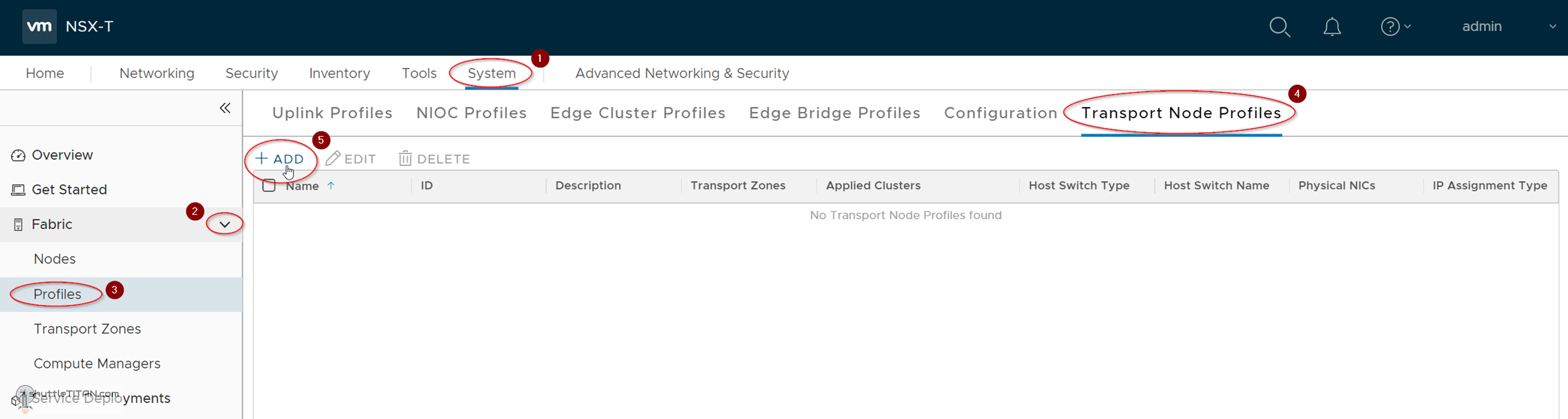
1. Click -> System ->Fabric -> Profiles -> Transport Node Profiles:
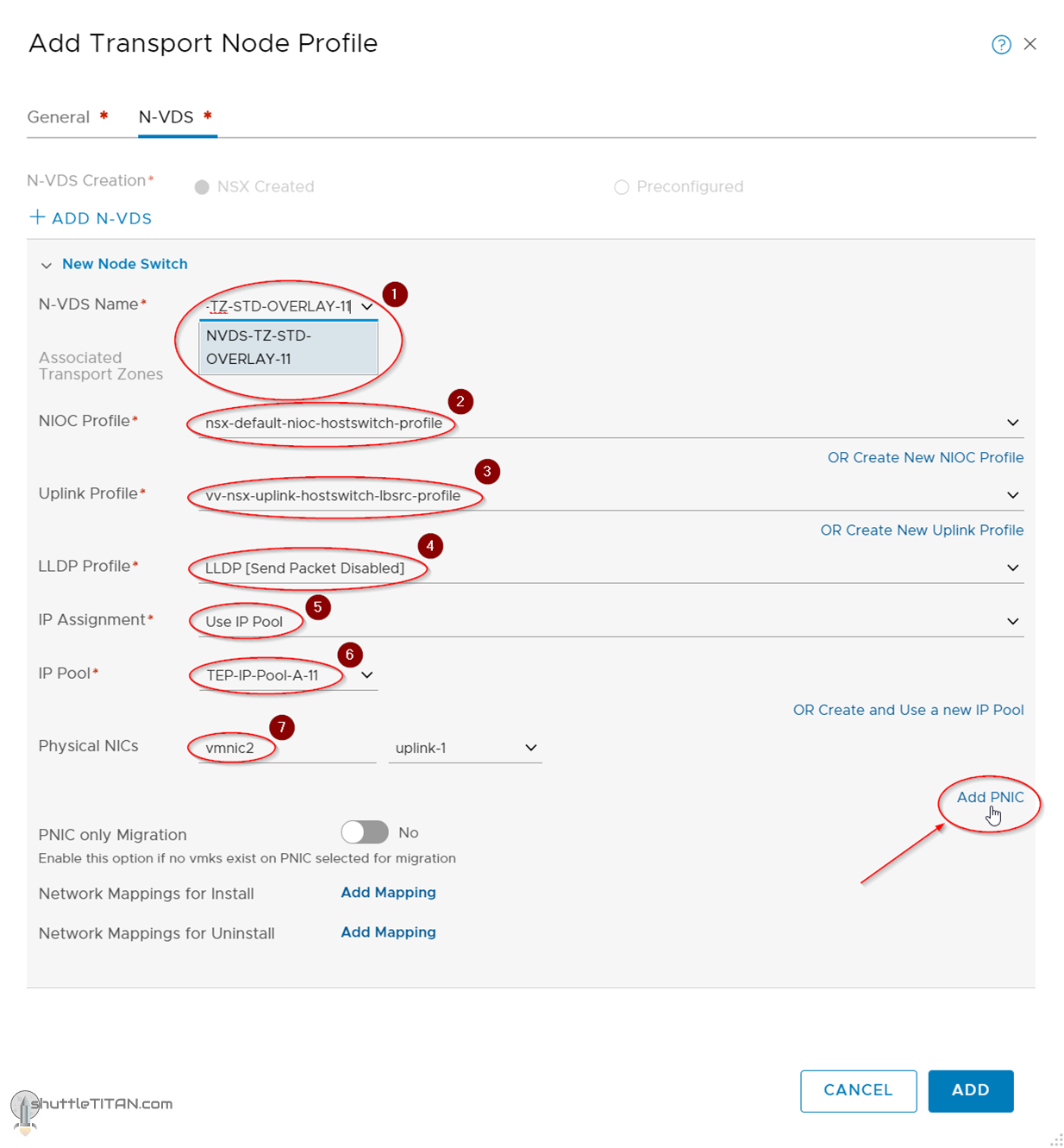
2. Specify the Name, select the “Overlay” Transport Zone created in Step 6, Click N-VDS as shown in the screenshot below:

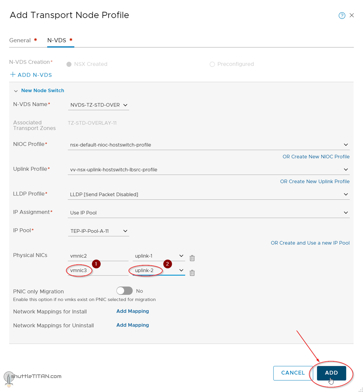
4. Select vmnic3 and uplink-2, click ADD as shown in the screenshot below:
Follow the same steps above to create another Transport Node Profile i.e. TNP-Compute-B-11 for Site B’s Hosts. The only change would be the TEP-IP-Pool-B-11 created in Step 5.
This concludes this step of creating a new Transport Node Profile successfully.
Let’s proceed ahead with the next blog in this series Step 9 – Configure Host Transport Node.