The previous step, discussed the “Transport Zones” (its types and limitations), N-VDS and step-by-step instructions to create vLan and Overlay Transport Zones. This blog is the “Step 7” of the NSX-T Installation series, where we will discuss “what is an Uplink Profile”, Compute Host’s networking design, Uplink Profile for Edge VM consideration and finally the step-by-step instructions to create one.
—————————————————————————————————————————————————————
But before we proceed, I would encourage you to briefly skim through my other blogs below, which you may find useful for this step:
- NSX-T Architecture (Revamped)for v2.4 and later
- Series Overview: Step 0 – High Level Design
- Preceding step: Step 6 – Create Transport Zones
If you are deploying this in your home lab or performing a PoC in a nested vSphere Environment, I would also suggest you have a quick glance of my blog Home Lab Setup – Nested ESXi Host’s networking for NSX-T.
—————————————————————————————————————————————————————
Let’s begin with the question – What is an Uplink Profile?
An uplink profile defines the policies for the links from hypervisor hosts to the logical switches (segments) or from NSX Edge nodes to top-of-rack switches i.e. teaming policies, active/standby links, VLAN ID and the MTU setting.
Uplink profile for Edge VM considerations:
- Standby uplinks are not supported with NSX Edge VMs using. For each uplink profile created for a VM-based NSX Edge, the profile must specify only one active uplink and no standby uplink.
- NSX Edge VMs now allows multiple uplinks on the same N-VDS for TEPs (Tunnel Endpoints). Each uplink can have one NIC with a distinctive name and IP address, “Load Balanced Source” teaming policy must be used for load balancing.
For load balancing – the hypervisor host must have two unused physical links available to be consumed by the N-VDS. However, for an NSX Edge’s tunnel endpoint and VLAN uplinks, can use a single physical link for fp-ethX links.
There are four pre-defined Uplink Profiles, which satisfies most use cases. This blog focuses on to create a bespoke uplink profile e.g. multi-tep uplink profile which will be utilised later in the series for the compute ESXi hosts.
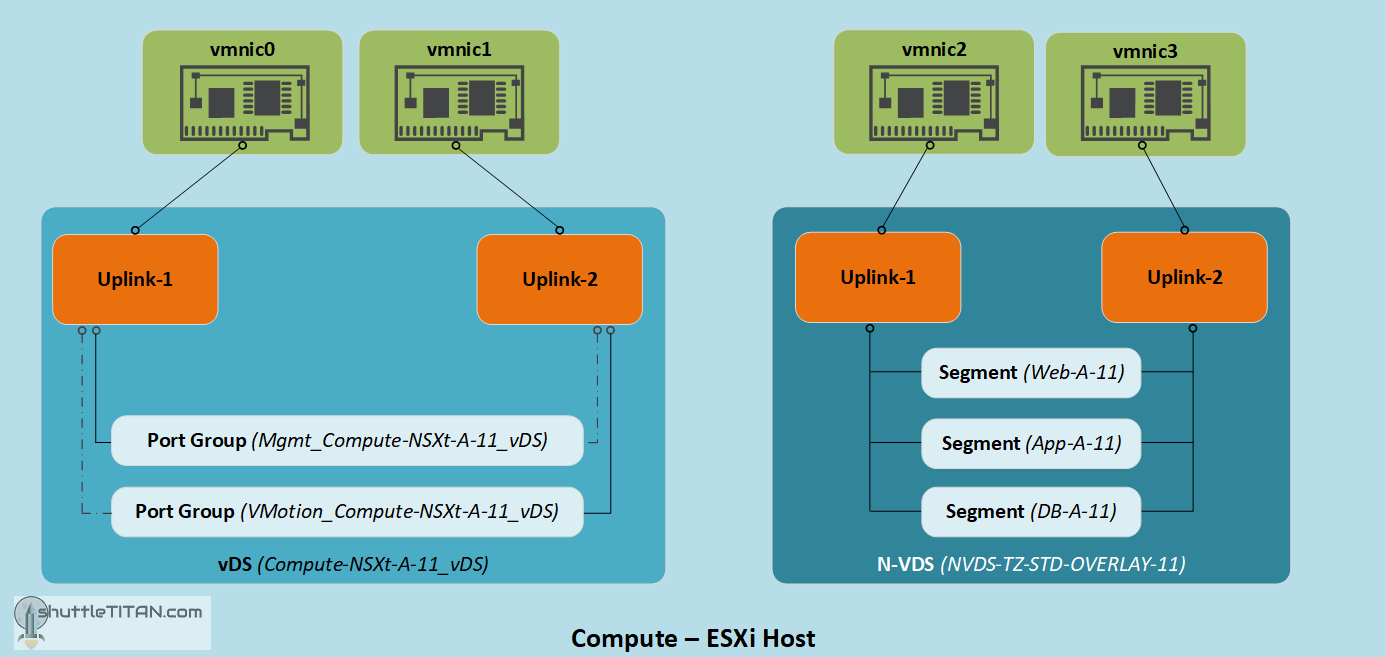
The design of the compute host’s “to-be” networking is illustrated in the image below:
Let’s get started…
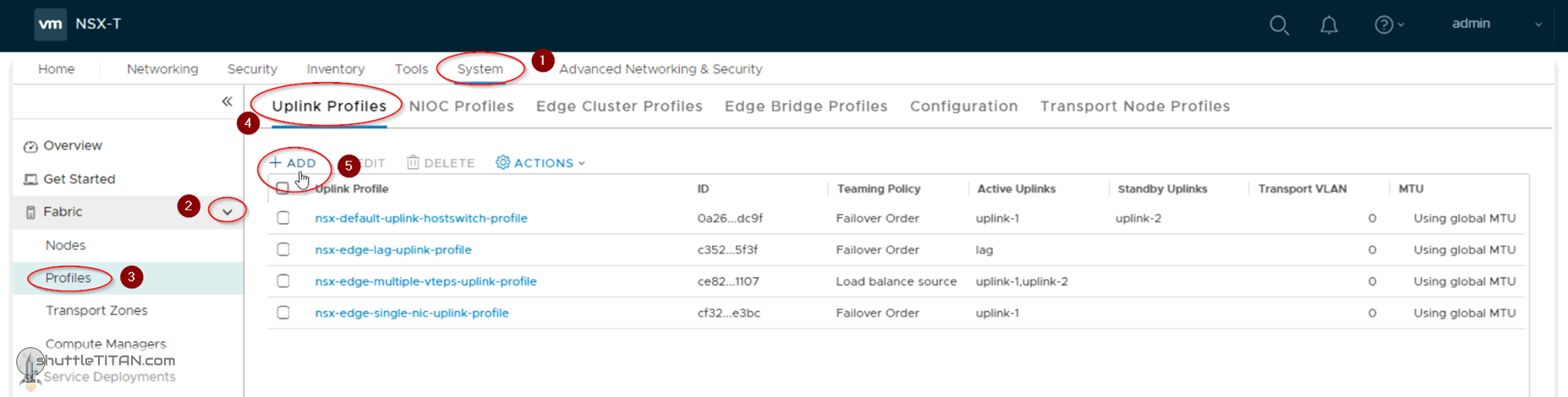
1. Click -> System ->Fabric -> Profiles -> Uplink Profiles -> Add:
Note: The four pre-defined uplink profiles as shown in the screenshot below:
2. Specify the name, select Teaming Policy as Load balance source and both uplink-1,uplink-2 as “Active Uplinks”:

Note: I have not specified any “Transport vLAN” in the screenshot above, as I am not using vLANs in this NSX-T Installation Series for simplicity, but for production environments you could specify the vLAN here, for all Host TEPs that get created in Step 9 – Configure Host Transport Node.
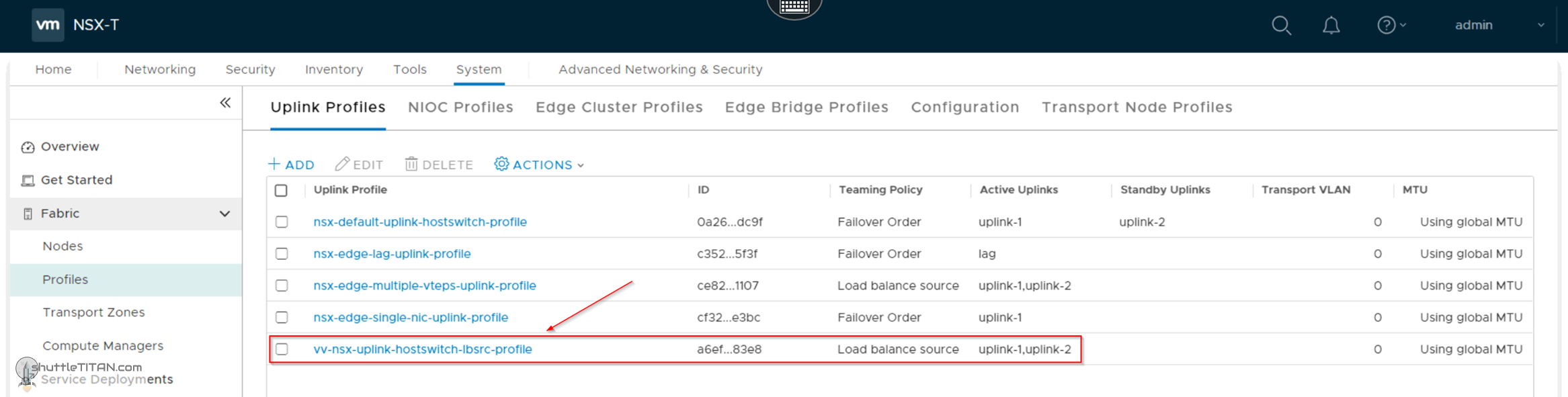
The screenshot below shows the new uplink policy created successfully:
This concludes this step of creating a new “Uplink Profile” successfully.
Let’s proceed ahead with the next blog in this series Step 8 – Create Transport Node Profile.