NSX-T v2.4 and later VMware introduced an architectural change that simplified the overall management, installation and upgrades; brought high availability, scalability along with flexible deployment options.
I opted to split the new architecture into two parts, for easier understanding:
- NSX-T Architecture (Revamped): Part 1 – talks about the new revamp NSX-T architecture and its components.
- NSX-T Architecture (Revamped): Part 2 (this blog) – talks about the NSX-T Agent/service communication between the NSX-T Manager Nodes and Transport Nodes.
In Part 1, we discussed the NSX-T architecture and how it extends the scope from on-premises to public clouds (and vice versa) and from VMs to containers.
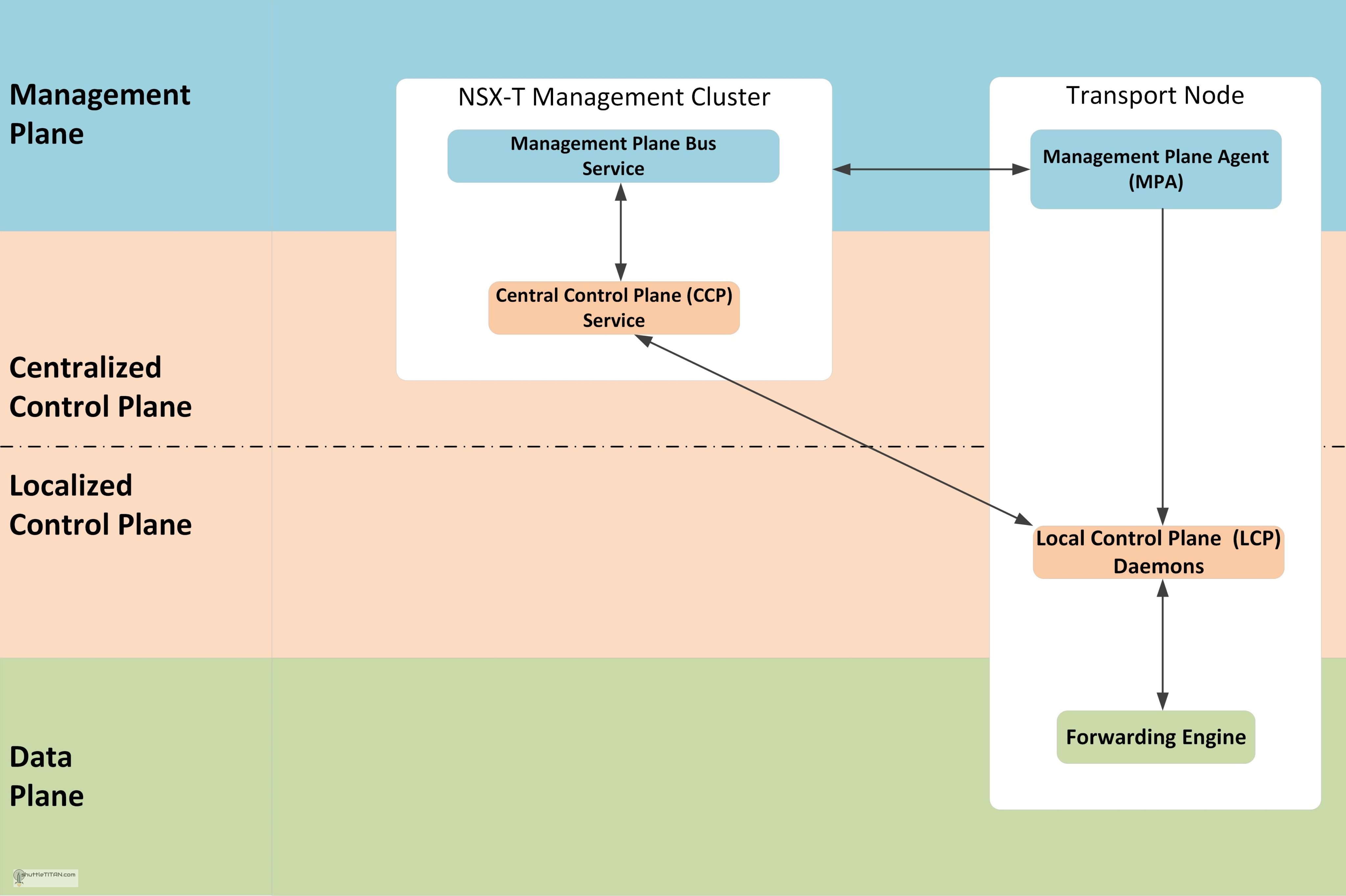
Let’s now talk about the NSX Agent/services that work behind the scenes for communication between NSX-T manager nodes and transport nodes. There are various modules of NSX that work in perfect harmony to form a robust and reliable system. Let’s use the same concept of management, control and data plane and the key agent component interaction in the following diagram to help visualise:
Management Plane Agent Communication
As discussed in the previous blog – NSX-T v2.4 introduced, the consolidation of management and centralized control plane in a single appliance. The NSX-T management Cluster is formation of three node which provides the entry point to NSX-T Datacenter, to perform operational tasks such as configuration and monitoring of all management, control, and data plane components. It is responsible for querying recent status and statistics from the control plane, and sometimes directly from the data plane.
Management Plane Bus service runs on each NSX-T Management Cluster node and is responsible for validating the configuration and storing a persistent copy locally. After successful validation, the configuration is pushed to the central control plane (CCP) service.
Management Plane Agent (MPA) runs on the Transport Nodes which is locally and remotely accessible. For monitoring and troubleshooting, the NSX-T Manager interacts with a host-based management plane agent (MPA) to retrieve DFW status along with rule and flow statistics. The NSX-T Manager also collects an inventory of all hosted virtualized workloads on NSX-T transport nodes. This is dynamically collected and updated from all NSX-T transport nodes.
Transport Node is a system which is capable of running an overlay, it can be a Host or an Edge Node.
Control Plane Agent Communication
Control plane provides control functions for logical switching, routing functions, etc., it is further segregated into two parts the Central Control Plane (CCP) and Local Control Plane (LCP).
CCP runs in the NSX-T Management Cluster nodes and is logically separated from all data plane traffic, any failure in the control plane does not affect data plane. It is responsible for providing configuration to the other cluster nodes and LCP. The CCP distributes the load of CCP-to-LCP communication i.e. the responsibility for transport node notification is distributed across the cluster nodes based on internal hashing mechanism. For example, for 60 transport nodes with three managers, each manager will be responsible for roughly twenty transport nodes.
LCP is a daemon, that runs in the Transport Node which monitors local link status and computes most ephemeral runtime state based on updates it receives from CCP and data plane, and pushes stateless configuration to forwarding engines.
Data Plane Agent Communication
Data Plane has a forwarding engine which deals with packets and its stateless forwarding following the tables/rules pushed by the control plane and handles the failover between multiple links and tunnels. It also maintains some state of features i.e. TCP termination. However, unlike the control plane where it manages the MAC/IP tunnel mapping and dictates how to forward the packets, the data plane forwarding engine is how to manipulate payload.
Let’s take a DFW Policy/rule enforcement example from the NSX-T documentation:
Management Plane flow: When a firewall policy rule is configured, the NSX-T management plane service validates the configuration and locally stores a persistent copy. Then the NSX-T Manager pushes user-published policies to the control plane service within Manager Cluster which in turn pushes to the data plane. A typical DFW policy configuration consists of one or more sections with a set of rules using objects like Groups, Segments, and application level gateway (ALGs).
Control Plane flow: NSX-T Control plane will receive policy rules pushed by the NSX-T Management plane. If the policy contains objects including segments or Groups, it converts them into IP addresses using an object-to-IP mapping table. This table is maintained by the control plane and updated using an IP discovery mechanism. Once the policy is converted into a set of rules based on IP addresses, the CCP pushes the rules to the LCP on all the NSX-T transport nodes.
Data Plane flow: On each of the transport nodes, once local control plane (LCP) has received policy configuration from CCP, it pushes the firewall policy and rules to the data plane filters (in kernel) for each of the virtual NICs. With the “Applied To” field in the rule or section which defines scope of enforcement, the LCP makes sure only relevant DFW rules are programmed on relevant virtual NICs instead of every rule everywhere, which would be a suboptimal use of hypervisor resources.


Awesome! Thank you so much for sharing.
Could you please make a post explaining the methodology you may follow to prepare for micro-segmentation?
Hi Way, thanks for reading.
I have few more blogs to write for the on-going NSX-T Installation series after which I will get to writing one for micro-segmentation 😉
This blog is really awesome !!
I have already shared to most of my participants. Very information.
Thanks for reading… “Knowledge increases by sharing it” 🙂
Nice blog………. you have explained it in very simplified way………… 🙂
thank you very much, now i know what is really nsx-t 🙂
Thankyou for writing such an awesome blog