This blog post is a continuation of the NSX-V routing design options for Metro/stretched cluster between two sites.
I would encourage you to visit the previous blog post here and get familiar with the background, pre-requisites and the routing design option 1 before going further.
Let’s recap the advantages of the Option 1:
- It helps decreasing licensing cost
- Optimizes the North / South communication to keep traffic local to the site-specific top of the rack switches.
- Helps sustaining a single site failure.
However, there was one disadvantage in the option 1 routing design regarding ESG VMs which as I mentioned is not major but may or may not raise concerns – What happens when you have a single ESG Failure at one site?
Looking at the configuration 2 x ESGs are deployed in ECMP mode per site – if one of them fails it will bring down half of the workload VMs N/S communication in the respective site, until the failed ESG VM is recovered by vSphere HA! Why?
Because the routing between the ESG VMs and UDLR is done via static routes. Unlike dynamic routes, static routes do not have a mechanism of identifying next hop failure and will keep black holing all traffic that is going North. Meaning – the network connectivity of half of the workload VMs is restored only when the ESG VM is recovered by vSphere HA on another ESXi Hosts and is back up and running successfully.
How to decrease the time of the network outage when one of the ESG VMs is down and recovering from vSphere – this is what this blog post is about 🙂
Option 2 – Summary of configuration:
- Universal DLR with Local Egress enabled and no control VM deployed
- Static routing between ESGs and UDLR
- 1 x ESG in HA mode and ECMP enabled per site
- 2 x Uplinks from the ESG to ToR switches
- vSphere DRS configured with “must run” rules for only the ESG VMs:
- 2 x ESG VMs (Active and Standby) for Site A “must run” on Site A ESXi Hosts
- 2 x ESG VMs (Active and Standby) for Site B “must run” on Site B ESXi Hosts
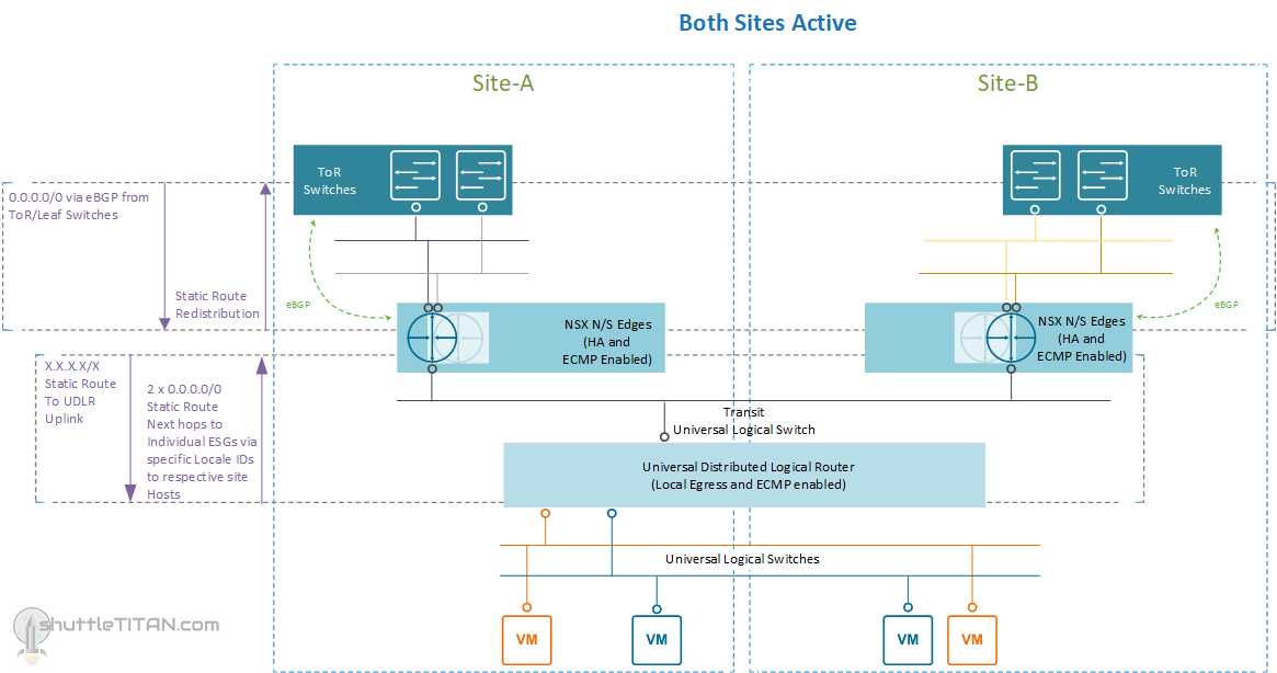
The only difference between the previously discussed Option 1 and this Option 2 is the ESG in HA mode. There will still be 2 ESG VMs but rather than having two active ESGs per site, there is only one active ESG and the other one as standby.
The advantage here comes with the ESG HA (not vSphere HA) – The active ESG VM maintains a heartbeat with the standby ESG VMs through an internal interface. If a heartbeat is not received within 15 seconds which is the default “Declared dead time” the standby ESG VM takes control and becomes active.
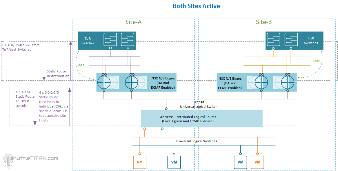
This options halves your N/S bandwidth as only one ESG VM is active at a time but it decreases the network downtime during a failure of ESG VM. One ESG VM provides 10 Gbps of bandwidth which should be adequate for small environments. Should you require more bandwidth, you can increase it by deploying another ESG in HA mode with ECMP enabled. The routing will then look like below:
The Site A, failure scenario will remain the same as mentioned in Option 1 – for more details please visit the part 1 blog post here.
Conclusion:
If your SLA is a bit relaxed and you can sustain half of your workload VM N/S communication loss, until the ESG VM is recovered via vSphere HA, then the previously discussed Option 1 here is a good routing design but if your SLA is strict, then option 2 of the ESGs in HA mode will make more sense.
The latter implies double the compute requirements as enabling HA mode on ESGs would deploy two appliances.
I hope this blog post was informative, please feel free to leave any comments or questions you may have.